Get in Touch with IDA

Solving Foaming Issues in Liquid Filling: A Practical Troubleshooting Guide

Contents
show
SOLVING foaming issues IN liquid filling begins with locating the point where the gas enters or exits the liquid. It doesn’t begin by slowing the filler. Watch the product from the holding tank to the filled container. Identify the first place where bubbles are repeatedly observed and change one controlled variable at a time. This approach distinguishes supply-side air entrainment from nozzle impact, dissolved-gas release, and persistent formulation-based foam.
A clean-looking bottle is not enough to prove that a correction worked. The same trial must also preserve net fill, cutoff behavior, product loss, and a useful cycle time. This guide takes a location-first diagnostic approach, provides a symptom-to-setting matrix, a controlled trial worksheet, and a supplier test package, without suggesting that one recipe is the answer to all challenges.
Effective foam control combines observation with measured process adjustments. When foaming occurs, identify the foam type and document its foaming behavior before trying to prevent foaming. That discipline makes foam management useful across filling technologies without promising that one setting can solve every product.
Start here: freeze the current recipe, capture a short video from a fixed angle, record product temperature and tank level, and mark the first place where bubbles become visible. Do not change pump speed, nozzle height, and fill profile together.
1. Foam Is a Location Problem Before It Is a Machine Problem
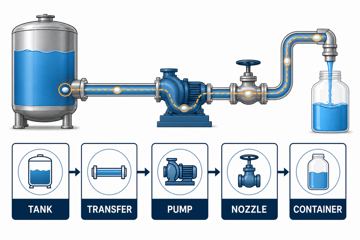
Nozzle foam is apparent to the operators. As such, they tend to focus on the nozzle for answers. In reality, the visible surface is the last observation point. Air may have entered through a low tank level, a vortex, a suction-side leak, an aggressive return line, or a pump condition several seconds earlier. It may also be dissolved in the product and released after a pressure change. The visible point of foam isn’t necessarily the point where gas enters the system.
Three questions will help you here. Where can gas enter the system? Second, where can dissolved gas be released or bubbles grow? Third, where does stable foam finally become visible? These questions are important because a slower nozzle speed can’t remove air that has been carried along through the supply hose. Conversely, rebuilding the supply system will not correct foam caused by a long free-fall distance inside the container.
University-hosted food-engineering research shows that foam formation and stability change with mechanical speed, liquid flow, temperature, formulation, and geometry. That’s a warning against single-cause assumptions. It isn’t a universal setting table: the actual process window still has to be established using the production product and container.
The practical rule: diagnose the first repeatable onset of bubbles, not merely the point where the foam becomes inconvenient.
2. Classify the Foam Before Changing a Setting
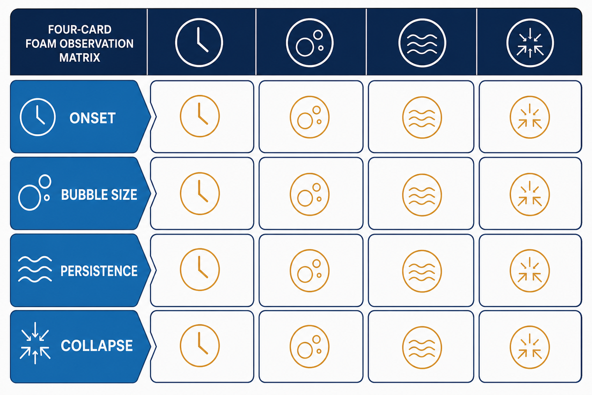
Foam onset and foam persistence are different observations. A surfactant or other surface-active ingredient can lower surface tension and change both foam generation and foam stability. A product can generate a large number of bubbles that rapidly collapse; and another can generate a small number of bubbles that remain stable and occupy the headspace. Document both. Note the bubble size, the point of onset, whether the foam continues to grow after cutoff, and how the surface changes during a consistent observation period.
| Observed symptom | Likely mechanism to test | Fast diagnostic check | First controlled action |
|---|---|---|---|
| Microbubbles are visible in the hose before filling | Upstream entrainment, suction leak, vortexing, pump shear, or gas release | Observe a clear section or sample before the nozzle | Stabilize supply conditions before editing the fill recipe |
| Foam begins when the stream strikes the container bottom | Free fall and impact | Compare the same recipe with a lower starting position | Test bottom-up travel or a gentler initial flow |
| Foam surges near the shoulder or neck | Restricted escape path, excessive late-stage velocity, or cutoff disturbance | Watch the final portion of the fill in slow motion | Test deceleration and cutoff timing |
| Foam persists long after filling stops | Product chemistry and stable films around bubbles | Compare collapse behavior at controlled temperature | Escalate formulation questions only after mechanical causes are isolated |
| Only one nozzle or lane behaves differently | Local restriction, seal, valve, alignment, or calibration issue | Swap or inspect the local component under safe procedures | Repair the local fault before changing the global recipe |
| Foam changes with tank agitation | Impeller-driven air incorporation or surface splashing | Repeat at a documented mixing state | Stabilize tank handling before nozzle trials |
| Detergent or aqueous product produces persistent fine bubbles | Surfactant foam with strong bubble films | Record collapse behavior after a fixed interval | Separate mechanical generation from formulation stability |
| Products containing suspended solid material change between batches | Product-condition variation | Compare representative batches under one controlled temperature | Define the tested product window |
| Foam rises only at elevated temperatures | Temperature-dependent viscosity, gas release, or stability | Repeat within the approved temperature range | Set a temperature boundary for the recipe |
This is the Foam Symptom-to-Setting Matrix. It’s a decision aid, not a promise that each symptom has one cause. E-PAK’s troubleshooting guidance similarly connects foaming with flow, turbulence, nozzle configuration, product behavior, and compatibility review. Use each row to choose the next test, then confirm the result.
3. Trace Air From Tank to Container With the Foam-Origin Ladder
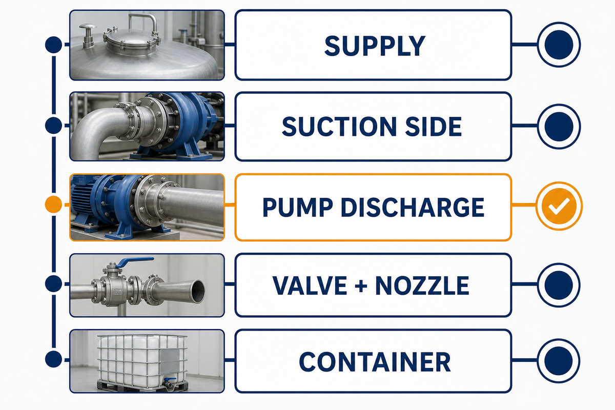
The Foam-Origin Ladder turns an open-ended complaint into a series. Start at the tank and follow the process downstream. Stop at the first point where the same bubble pattern appears on repeated runs. If observation is not possible at one point, use a safe sample port, sight glass, or temporary diagnostic arrangement approved for the product and process.
- At the tank, look at level, check for vortexing and splashing, review the position of the return line, check mixing, temperature and dwell time.
- Look at the joints, seals, clamps, hoses and inlet restrictions on the suction side, and determine if the pump is starved.
- Compare sound and pressure and look at product condition before and after pumping.
- Check for high points, sharp restrictions, and abrupt changes in direction and review recirculation and trapped gas along the transfer path.
- At the valve and nozzle, check opening behavior, restriction, nozzle diameter, starting height, travel, and cutoff.
- Inside the container, observe free fall, wall impingement, neck restriction, wetting, and the escape route for displaced air. Observe how air escapes and review if the air is being displaced.
Oden Machinery’s troubleshooting guide links transfer turbulence, pump speed, and fill speed with air bubbles and inconsistent volume. This supports a firm boundary: air already present upstream can’t be corrected reliably by nozzle tuning alone.
The cause of foam formation can be a combination of process conditions. It doesn’t mean that a calm surface indicates that gas isn’t present within a liquid. A calm surface does not prove that no gas exists within a liquid, and long-term foam behavior can differ from the original foam seen at cutoff. Track conditions that cause foaming rather than treating the filled container as the only diagnostic point.
How can you tell whether the nozzle is the real origin?
Take a sample of the product before it’s discharged and sample the product immediately after the stream enters the container. If the supply sample is clear but bubbles appear at impact, nozzle position, velocity, or container geometry becomes a stronger lead. If microbubbles are already present, first stabilize the supply. Often a single sample captures one condition in the supply. Taking multiple samples may give a better idea of what’s actually occurring.
4. Stabilize the Supply Side Before Tuning the Nozzle
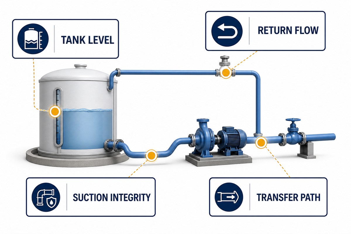
Stable fillers can’t make up for unstable feeds. Keep the product condition repeatable during testing. Use a single batch or a documented equivalent, a controlled temperature range, representative tank level, and intended recirculation state. Temperature can affect viscosity, gas release and foam persistence. Record flow rates and downtime as operational outcomes rather than assuming one root cause.
Prevent excessive air from entering at the tank and suction side before attempting downstream defoaming. Better supply stability can significantly reduce spills, reduce waste, and protect production schedules. It won’t eliminate the need to verify the nozzle recipe, but it takes away a moving target.
- Position return flow to avoid splashing above the liquid surface where the process permits.
- Maintain enough liquid depth to reduce vortex formation at the outlet.
- Inspect the suction side for small air paths that may not leak liquid outward.
- Check whether the bubble pattern changes with pump speed, restriction or starvation.
- Remove avoidable high points and trapped-gas pockets in the transfer route.
- Keep mixing and recirculation conditions identical between trials.
Don’t adjust equipment while it’s operating, follow line isolation, sanitation and maintenance procedures. The goal is to get a repeatable incoming condition to the nozzle for the next test to have meaning.
5. Tune Nozzle Position, Fill Profile, and Cutoff
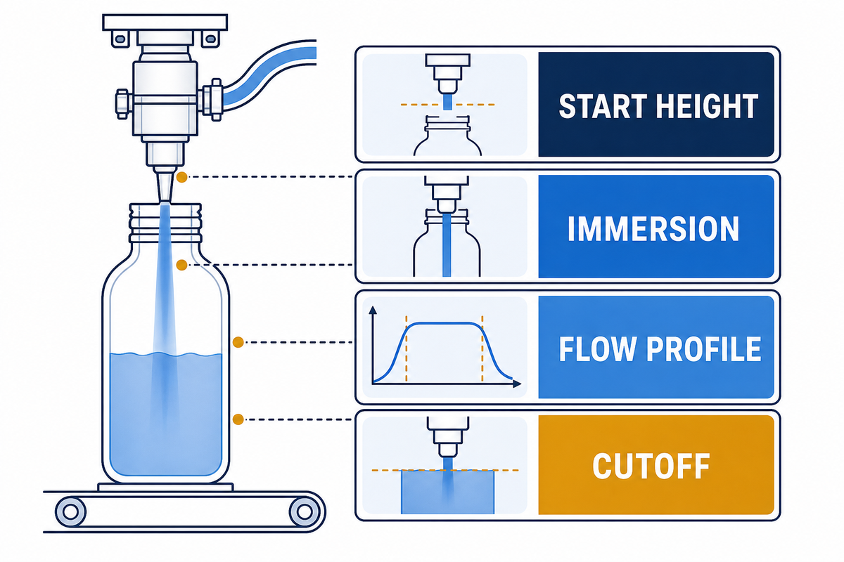
Once the supply is stable, establish a baseline and adjust the part of the recipe that corresponds to the observed symptom. A bottom-up movement keeps the outlet close to the rising liquid and can reduce the free-fall distance. Filamatic describes bottom-up position and dual-speed adjustment as controls that can be tuned for foam reduction and production rate.
A staged profile often begins gently and uses a higher, faster middle flow when the outlet is in a favorable position, and then slows and decelerates just before cutoff. Starting height, immersion, acceleration, main flow, deceleration, final flow, and cutoff delay are separate variables. Change only one during initial isolation.
The slowest possible fill isn’t always the best. It may reduce impact yet allow the nozzle to dwell in an unfavorable position, extend exposure to an unstable feed condition, or destroy required throughput. The goal is to set the nozzle speed as fast as possible to satisfy foam, accuracy, loss, hygiene, and container-wetting criteria—not simply the lowest speed.
Filling equipment should be assessed under the conditions of production line. Different flow rates may introduce air into the product at different stages, while excessive foaming may delay bubbles to collapse before capping. Recipe work should balance product quality and throughput.
Configuration boundary: this article owns troubleshooting. For the commercial differences among metering methods, nozzles, and complete liquid filling machine configurations, use the equipment category page and validate the shortlist with representative product trials.
6. Choose Hardware by the Foam Mechanism
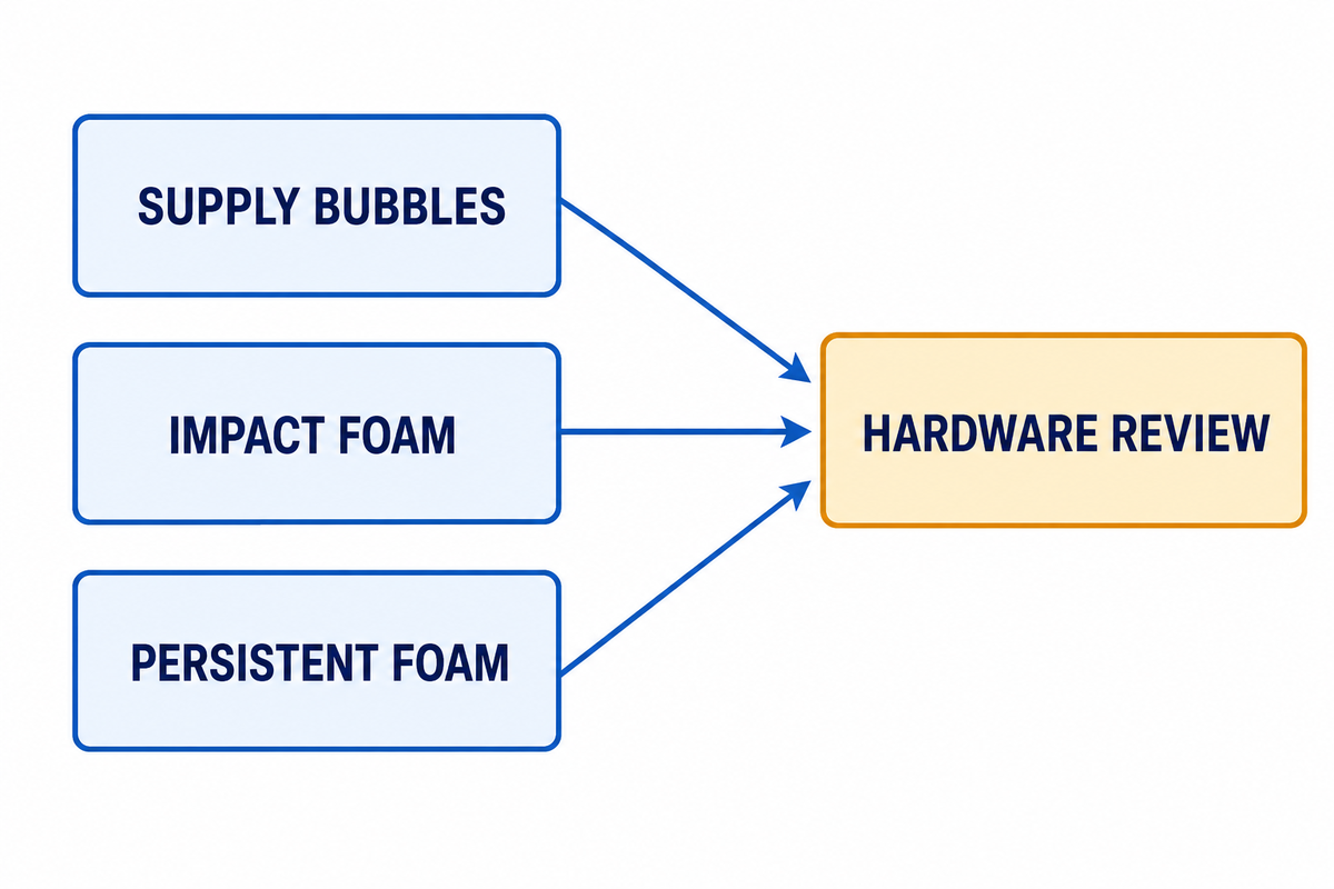
Hardware should follow the diagnosed mechanism. A diving nozzle can reduce free fall, but its travel, outside wetting, contact risk, stringing, and cleaning requirements must fit the container and product. A larger flow path may lower liquid velocity at a given flow, yet it also changes cutoff and capillary behavior. Packaging Digest notes this tradeoff between nozzle diameter, velocity, splashing, foaming, and capillary action.
| Mechanism observed | Hardware direction to investigate | What must be verified |
|---|---|---|
| Free-fall impact | Bottom-up or diving-nozzle movement | Travel clearance, hygiene, wall wetting, cutoff, and cycle time |
| High exit velocity | Flow-path or nozzle-geometry review | Accuracy, dripping, capillary behavior, and valve response |
| Fill-to-level requirement with manageable recirculation | Overflow principle evaluation | Product return behavior, sanitation, aeration, and container consistency |
| Upstream entrainment | Pump, inlet, transfer, or tank correction | Whether incoming product is bubble-free before changing the filler |
| Persistent formulation-driven foam | Joint process and formulation review | Product performance, compliance, cleaning, and shelf-life effects |
Liquid Packaging Solutions describes a rising bottom-up nozzle as one way to reduce agitation and distinguishes it from overflow filling. Historical patent literature also treats antifoam filling as a coordinated container, nozzle, flow, and foam-removal problem rather than a single speed setting. Neither source proves that one filler technology is universally best.
Many applications can share the label “foamy” while requiring different solutions to address the mechanism. Proper equipment selection does not guarantee proper aeration; in packaging, the usual aim is to limit unwanted air incorporation. Use the failure mechanism to identify the hardware for testing.
7. Run a One-Variable Fill Trial
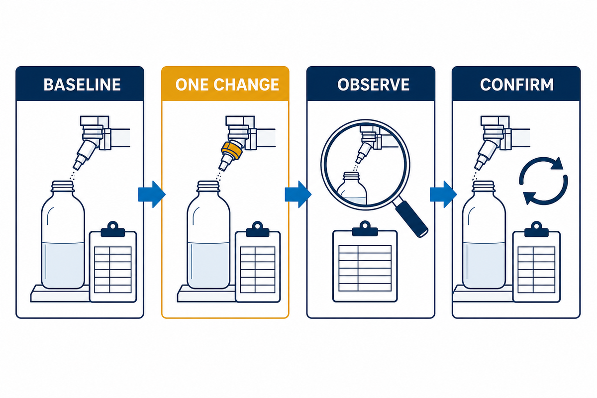
A One-Variable Fill Trial is the quickest defensible way to distinguish an initial cause. Freeze the baseline, isolate the variable, run a sufficient number of containers to show repeatability, note the effect, and assess the cost. One-variable testing cannot reveal every interaction, so the winning candidate must later be confirmed across the intended product and operating window.
For each specific foam symptom, differentiate foam levels during filling from existing foam after cutoff. Managing foam means recording whether foam forms at impact, during nozzle withdrawal, or after pressure release. A result should provide long-term recipe confidence, not just one clean container.
| Trial field | What to record | Why it matters |
|---|---|---|
| Product state | Batch, temperature, dwell, mixing, tank level | Prevents a product change from being mistaken for a setting effect |
| Fixed baseline | Recipe, hardware, container, supply arrangement | Makes comparisons traceable |
| Single change | Exact parameter or component changed | Supports initial cause isolation |
| Foam onset | First location and time in the cycle | Separates gas entry, gas release, and visible foam |
| Foam persistence | Surface condition and collapse behavior at a fixed observation time | Distinguishes formation from stability |
| Fill outcome | Net fill result, variation, wet containers, spills, drips | Prevents a cosmetic improvement from hiding accuracy or loss |
| Production outcome | Cycle time, interruptions, cleanup, operator intervention | Shows the real operational tradeoff |
When has a foam trial actually passed?
A trial passes only if the pre-agreed acceptance criteria are concurrently achieved. A trial that reduces the foam crown but results in underfills, unstable cutoff, wet containers, or unacceptable cycle times hasn’t passed. After initial isolation, vary representative product temperature, tank level, and normal operating conditions to expose interactions that a one-variable screen cannot show.
A published equipment case study describes a solution combining inlet control, a long filling lance, ramped speed, pump and recirculation components. The useful lesson is the coordinated diagnosis, not its specific pump rating or pressure; those figures belong to that installation and must not be transferred as a general recipe.
8. Know When Formulation Help Is Appropriate
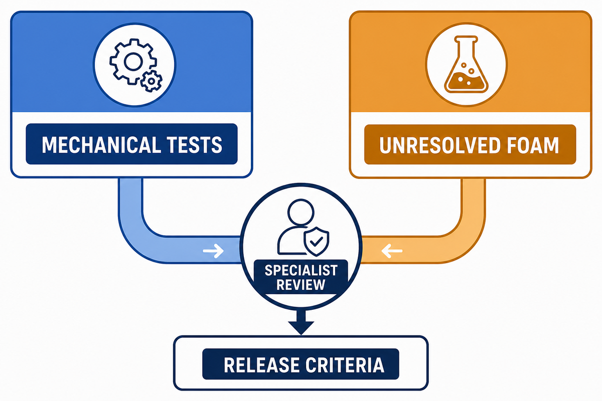
When the supply is stable, likely mechanical variables are tested, and persistent foam follows the product across reasonable configurations, don’t change machine settings any more. Escalate with trial records, samples, photos or videos and explain the process window. This provides evidence rather than a vague request to “remove the foam.”
No universal additive or foam-control standard was found during the current research; product requirements remain the controlling boundary. A defoamer or antifoam is a formulation decision and should be reviewed accordingly. Its compatibility, performance effects, labeling, processing, sanitation, and regulatory implications may need product-specific review.
Terms like anti-foam, defoaming, and low concentrations don’t define a safe use level. Solvent-based and aqueous products may react differently, and a surface-active ingredient may help achieve one parameter while affecting another. Formulation review protects product quality and avoids substituting ongoing chemical treatment for a fixable mechanical cause.
What should happen before an additive trial?
Document the unresolved mechanism, confirm who owns formulation approval, define what product attributes cannot change, and establish the test and release criteria. Mechanical adjustments and formulation changes should not be mixed in the same trial because the result becomes hard to interpret.
9. Build a Foam-Prone Product Test Package
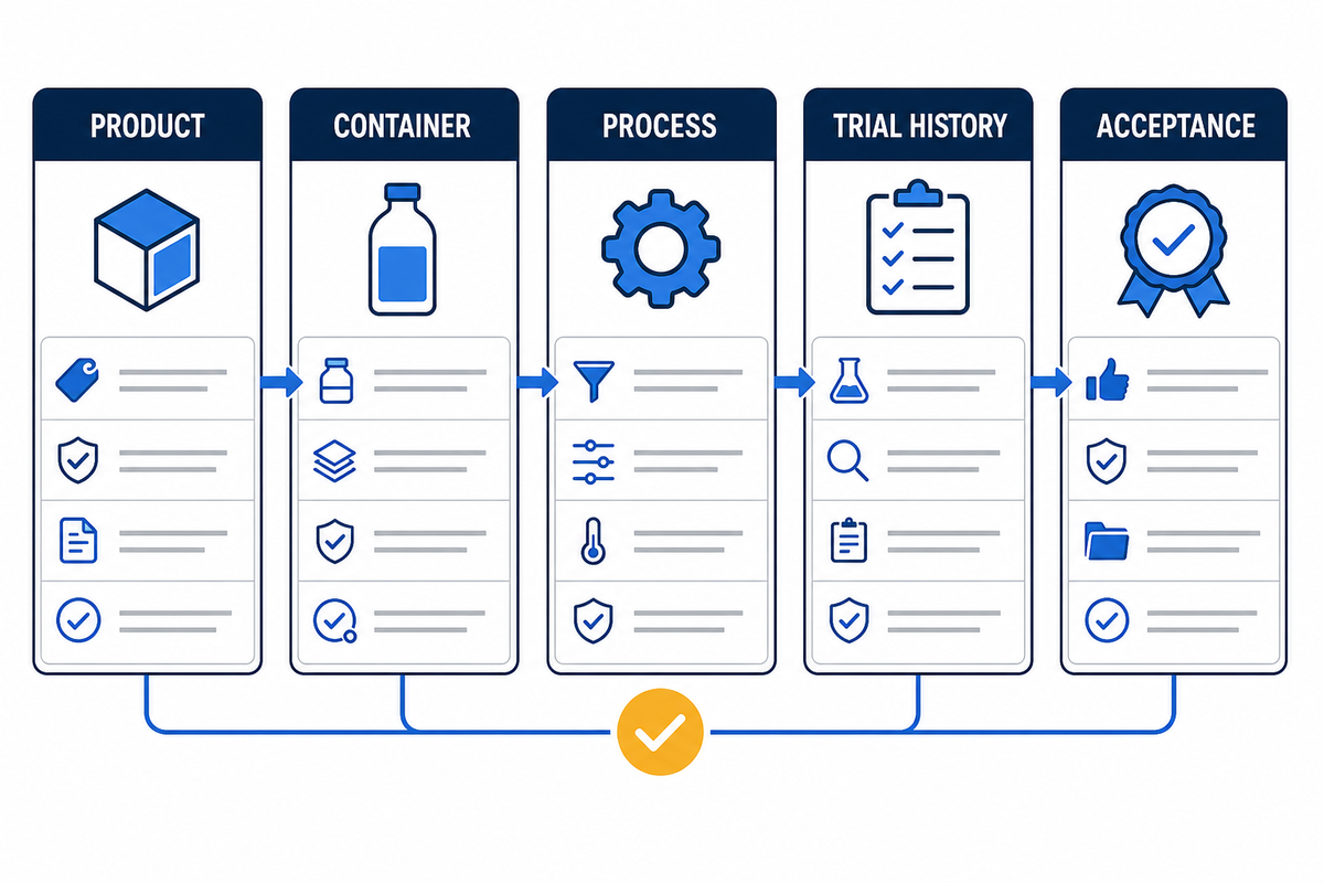
A supplier can’t reproduce a foam problem from a product name, bottle volume and speed alone. Use the Foam-Prone Product Test Package to provide the actual working condition. This is a practical procurement method, not an industry standard.
- Representative product details: material, composition constraints, viscosity or flow behavior across the intended temperature range, and handling limits.
- Container and closure evidence: drawings or samples, neck geometry, material, target headspace, and acceptable wetting condition.
- Process requirements: target fill, accuracy criteria, speed range, tank and transfer arrangement, sanitation needs, and changeover expectations.
- Foam evidence: fixed-angle video, first onset location, bubble appearance, persistence, and the conditions under which the problem worsens.
- Trial history: baseline, variables tested, results, rejected approaches, and unresolved tradeoffs.
- Acceptance criteria: fill result, foam/headspace condition, product loss, cutoff, container cleanliness, cycle time, and repeatability window.
Ask the supplier to state the tested product condition and the settings or hardware used, then repeat the result across the agreed range. A single attractive demonstration bottle is not a commissioning window. Preserve the approved recipe, setup notes, and visual reference so production operators can recognize drift later.
The package should also capture foam-related cleanup, lost material, and any effect on production schedules. These records help compare process adjustments and filling technologies on the same acceptance criteria. They also show whether a proposed change can prevent foaming without shifting the problem elsewhere.
Ready to discuss the equipment boundary?
Bring the completed test package when you discuss a suitable filling-machine configuration with IDA Equipment. The evidence helps narrow a trial plan without turning this troubleshooting guide into a duplicate product-selection page.
Bring the completed test package when you discuss a suitable filling-machine configuration with IDA Equipment. The evidence helps narrow a trial plan without turning this troubleshooting guide into a duplicate product-selection page.
Frequently Asked Questions
Why does liquid foam during filling?
Foam appears when gas is introduced or released and the liquid can keep the resulting bubbles stable. Gas may enter through vortexing, splashing, a suction leak, pumping, free fall, or impact. It may also come out of solution after pressure changes. Find the first repeatable bubble location before assuming the nozzle is responsible.
How do I reduce foam without making the filling line too slow?
Obtain a stable tank and supply and capture a baseline. Stabilize the tank and supply, record a baseline, then change one variable such as nozzle position, initial flow, main flow, deceleration, or cutoff. Measure foam onset and collapse together with fill result, loss, and cycle time. A staged profile may capture useful middle flow, but it has to be verified on the final product and container.
Is bottom-up filling always best for foamy liquids?
Not necessarily. Bottom-up filling can reduce free fall by keeping the outlet close to the rising liquid, but nozzle geometry, container neck, hygiene, contact risk, dripping, product behavior, and speed still matter. Make sure nozzle travel reduces foam without creating a new quality or sanitation problem under the intended operating range.
Can I use a defoamer to solve filling foam?
Treat a defoamer as a formulation change, not a routine machine adjustment. Product owners and appropriate specialists may need to review compatibility, performance, sanitation, labeling, and regulatory effects. This guide doesn’t recommend an additive or dosage.
Which filling machine is suitable for a foamy liquid?
The answer depends on where the foam begins, product flow behavior, container geometry, accuracy and speed targets, hygiene requirements, and cutoff behavior. Different configurations such as diving-nozzle, staged-flow, overflow, piston, pump, and gravity tackle different issues. First diagnose the mechanism, then with representative product tests, confirm the apparatus and recipe.
What information should I record during a foam trial?
Record the batch, temperature, tank level, line arrangement, active recipe, one changed variable, first bubble location, foam onset and collapse behavior, net fill result, spills or wetting, cycle time, and operator observations. Fixed-angle photos or video make comparisons easier to review.
References & Sources
- Purdue University-hosted study on foam formation and stability
- US FDA guidance used for the product-specific quality boundary
- Packaging Digest: capillary nozzle tradeoffs
- US3415294A: historical antifoam filling patent
- Liquid Packaging Solutions: bottom-up filling principles
Learn more about IDA Equipment, review the broader filling machine guide, or use the site’s contact page when you have a complete product test package.