Get in Touch with IDA


Industrial mixing is the mechanical unit operation that transforms multiphase blends, dry powders, and high-viscosity pastes into uniform batches. Engineers accomplish effective mixing and consistent mixing performance when the geometry of the impeller is properly designed with respect to shaft speed and baffling. Tank volume alone never determines the correct process duty.
Modern chemical, coating, battery slurry, and food production lines span any wide range of viscosities from 1 cP solvents to 1,000,000+ cP pastes. An axial hydrofoil that suspends solids in 500 cP will stall in a 50,000 cP resin vessel. Running a high speed, saw tooth blade in a low viscosity storage tank is a waste of motor power and doesn’t improve bulk turnover.
Direct Answer: Industrial mixing uses axial hydrofoils for bulk circulation and solids suspension in low viscosity liquids. For high-viscosity pastes from 50,000 to 1,000,000+ cP, coaxial multi-shaft and double planetary mixers provide wall-sweeping turnover and kneading.
Key Engineering Takeaways (TL;DR)
- Scale-up trap: For geometrically similar turbulent mixers at unchanged density and power number, holding tip speed constant during a 10x volumetric scale-up cuts specific power to approximately 0.46x. Blend time must be verified for the specific vessel geometry.
- Viscosity handoff: Open-tank turbines lose radial circulation in high-viscosity pastes. Saw-tooth Cowles blades require a wall-scraping anchor or butterfly blade above 50,000 cP.
- Inline vs batch boundary: Charles Ross Co. reports self-pumping up to 10,000-20,000 cP with its inline rotor-stator mixers. Their 10 HP, 240 gpm recirculation example uses a water-like fluid.
- Seal and safety compliance: A pressurized dual mechanical seal limits process fluid leakage. For operation at -0.098 MPa, both the vessel and seal must be rated for that pressure, and any drive installed in a hazardous area must be suitable for that area.
| Quick Specification Parameter | Verified Engineering Range | Governing Standard or Primary Source |
|---|---|---|
| Operating Viscosity Span | 1 cP to 1,000,000+ cP | University of Michigan ChE 344 / IDA Equipment Portfolio |
| Reynolds Number Regimes (Re) | Laminar (<10), Transitional (10–10,000), Turbulent (>10,000) | AIChE Chemical Engineering Progress (CEP) |
| Impeller-to-Tank Diameter Ratio (D/T) | 0.20–0.60 (turbines, 0.33 baseline); 0.90–0.98 (anchors/ribbons) | MXD Process Sizing Guide / University of Michigan |
| Specific Power Input (P/V) | 0.1–0.3 kW/m³ (gentle blend) to 1.0–5.0 kW/m³ (dispersion) | MDPI Energies Stirred-Tank Study (2025) |
| Vessel Vacuum & Seal Rating | Vacuum degassing to -0.098 MPa; API 682 Plan 52 / 53A/B/C seals | API Standard 682 / ATEX Directive 2014/34/EU |
How Do Industrial Mixing Mechanisms Divide Duties Across Viscosity Regimes?
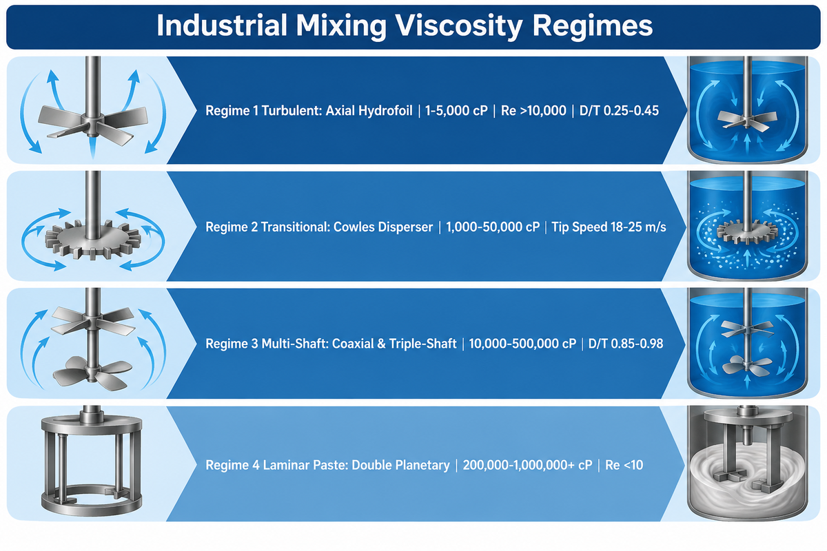
Industrial mixing processes divide duties into four viscosity regimes defined by the impeller Reynolds number (Re). Axial-flow impellers are prevalent below about 5,000 cP, where turbulent flow occurs when density, speed, diameter, and viscosity produce Re above 10,000. High-speed dispersers operate about 1,000 to 50,000 cP. Coaxial butterfly and triple-shaft systems operate in overlapping bands from 10,000 to 500,000 cP, while double planetary mixers handle about 200,000 to 1,000,000+ cP.
In fluid dynamics, two dimensionless numbers describe how an industrial mixer transfers mechanical energy into a liquid mix. The AIChE Chemical Engineering Progress guide on difficult mixing problems defines impeller Reynolds number (Re = ρND²/μ) as the ratio of inertial to viscous forces. Stability of flow data in the AIChE Journal on Reynolds number and impeller diameter effects further describes the power number (Np = P / [ρN³D⁵]) which relates shaft torque to blade geometry.
“Impellers are classified as either laminar (viscous) or turbulent mixers. For very viscous fluids in the laminar mixing regime, the impeller diameter approaches the tank diameter in close-clearance ribbon, screw, and anchor designs.
This table compares impeller choices for four viscosity regimes using Reynolds number, D/T, tip speed, and mixing mechanism. This classification matrix pairs each viscosity band with the mixing element geometry that sustains bulk flow without cavitation.
| Impeller Type & Regime Class | Viscosity Band (cP) | Reynolds Number (Re) | Diameter Ratio (D/T) | Tip Speed (m/s) | Dominant Mixing Mechanism |
|---|---|---|---|---|---|
| Marine Propeller (Regime 1: Turbulent) | 1–2,000 cP | >10,000 | 0.20–0.35 | 3.0–6.0 m/s | Axial pumping for low-viscosity liquid blending |
| Axial Hydrofoil Impeller (Regime 1: Turbulent) | 1–5,000 cP | >10,000 | 0.25–0.45 | 2.5–5.5 m/s | Low-Np (0.3) axial turnover and solids suspension |
| Pitched-Blade Turbine (Regime 1–2: Mixed Flow) | 100–10,000 cP | 1,000–10,000+ | 0.30–0.50 | 3.0–6.5 m/s | Combined axial and radial shear (Np ~1.3) |
| Rushton Flat-Blade Turbine (Regime 1–2: Radial) | 1–10,000 cP | 1,000–10,000+ | 0.25–0.40 | 3.5–7.0 m/s | High-power radial gas-liquid dispersion (Np ~5.0) |
| Cowles Saw-Tooth Disperser (Regime 2: Transitional) | 1,000–50,000 cP | 100–10,000 | 0.25–0.35 | 18.0–25.0 m/s | High-speed tip shear for pigment deagglomeration |
| Coaxial Butterfly Disperser (Regime 3: High Viscous) | 10,000–150,000 cP | 10–500 | 0.85–0.95 | 1.5–3.0 / 18 m/s | Butterfly folding plus high-speed dispersion disc |
| Triple-Shaft Vacuum Mixer (Regime 3: Multi-Shaft) | 50,000–500,000 cP | 10–100 | 0.90–0.98 | 0.5–2.0 / 25 m/s | Anchor wall scraping, tooth dispersion, rotor-stator shear |
| Double Planetary Mixer (Regime 4: Laminar Paste) | 200,000–1,000,000+ cP | <10 | 0.90–0.98 | 1.5–3.5 m/s | Orbital positive-displacement kneading without dead zones |
Turbulent Axial and Radial Flow Below 10,000 cP (Hydrofoils vs. Rushton & Pitched-Blade Turbines)
In low-viscosity liquids where density, speed, and diameter create turbulent eddies (Re above 10,000), fluid momentum carries across the entire mixing vessel. As explained in the University of Michigan ChE 344 reactor mixing guidelines, axial impellers such as marine propellers and hydrofoils pump liquid parallel to the shaft. This axial mixing action provides efficient mixing and suspension of off-bottom solids with low energy consumption.
Radial flow Rushton disk turbines eject fluid horizontally against the tank wall. That radial stream generates high shear forces for gas-liquid dispersion. However, a Rushton turbine draws roughly 16 times more shaft power than an equal-diameter hydrofoil at the same speed because its power number is 5.0 versus 0.3.
Transitional High-Speed Dispersion From 1,000 to 50,000 cP (Cowles Saw-Tooth Blades & Coaxial Butterfly Systems)
Once batch viscosity climbs above 5,000 cP, viscous drag dampens turbulent eddies outside the impeller zone. To break down pigment agglomerates and disperse fillers into coatings, engineers deploy a high-speed disperser with a saw-tooth Cowles blade. Industrial hydraulic-lift units run up to 1,500 rpm, while laboratory models reach 3,000 rpm to generate tip speeds of 18 to 25 m/s.
Saw-tooth Cowles dispersers lose radial circulation when batch viscosity exceeds 50,000 cP, creating stagnant wall zones unless paired with a low-speed anchor or butterfly scraper. For shear-thinning pastes between 10,000 and 150,000 cP, a coaxial butterfly disperser mixer pairs a top-folding butterfly frame with a high-speed toothed disc. These coaxial mixers offer rapid bulk feeding into the local shear zone.
Laminar Positive Displacement Above 50,000 to 1,000,000+ cP (Triple-Shaft & Double Planetary Mixers)
Bulk circulation weakens above 50,000 cP. The impeller Reynolds number still depends on mixer geometry, speed, and fluid properties. Instead of relying on turbulent jet eddies, the impeller must physically sweep the vessel cross-section. Distributed blades rotating on dual axes fold material across the full diameter of the vessel, as shown in US Patent Application US20150224460A1 on planetary impeller kinematics.
How Should Engineers Size an Industrial Mixer Using D/T Ratio, Tip Speed, and Power Input?
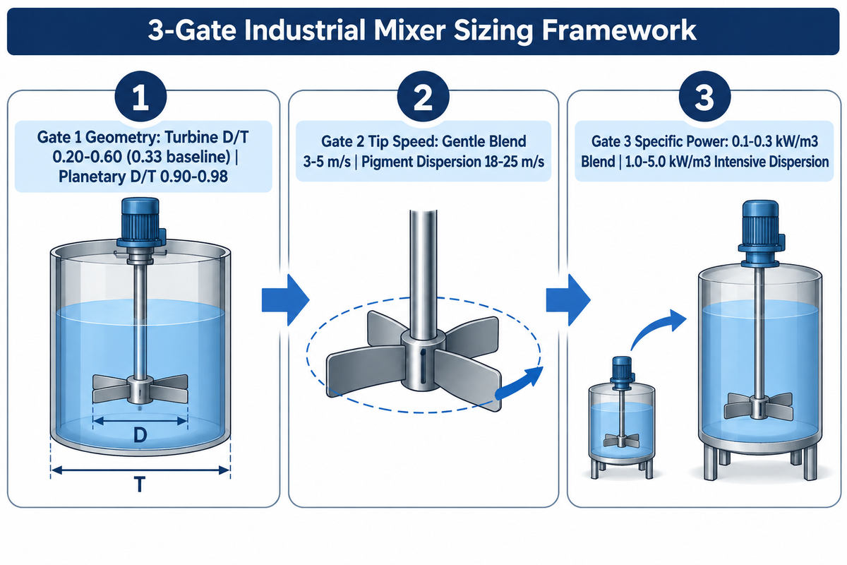
Size an industrial mixer by checking tank geometry, blade kinematics, and shaft power. Start with an impeller-to-tank diameter ratio (D/T) of 0.20–0.60 (0.33 baseline) for conventional turbines, while wall-sweeping and planetary designs require 0.90–0.98. Then match tip speed and specific power to the duty: the examples below range from 0.1–0.3 kW/m³ for gentle blending to 1.0–5.0 kW/m³ for intensive dispersion.
Sizing errors occur mainly because of ignoring tank geometry and specific mixing requirements, and not because of the quality of the motors. The liquid height, impeller count, and diameter ratio jointly control turnover time. Experimental data from the turbulent blend time thesis from the University of Dayton shows that for a given geometry, controlling turnover time is largely a function of changing the impeller count and the diameter ratio.
Gate 1, Impeller-to-Tank Diameter Ratio (D/T) and Baffle Geometry for Bulk Turnover
As stated in the MXD Process tank-to-impeller sizing guide, most turbine mixing systems operate well with a D/T ratio of 1/5 (0.20) to 3/5 (0.60). The standard baseline is 1/3 (0.33) of inside tank diameter, such as an 8-inch impeller inside a 24-inch vessel. The blade should be placed 1/3 of tank height from the bottom of the tank.
Low-viscosity cylindrical tanks employ four wall baffles (each width T/12) to break up swirl into vertical mixing. Acc. To Dr. Dave Dickey in Chem. Eng. Mag.’s guide to good mixing, a deep surface vortex indicates mixing efficiency, or liquid, where fluid spins in a circle and entrains air. For 1,000 L totes with a 150 mm (6-inch) cap, a folding-blade IBC tank mixer passes through the narrow opening and expands inside to restore proper D/T geometry.
Gate 2, Tip Speed Boundaries for Solid-Liquid Suspension vs. Pigment Deagglomeration
Rotational speed in rpm is meaningless without blade diameter. Peripheral tip speed (v_tip = πDN, with N in revolutions per second) describes blade-edge velocity, while local shear rate also depends on clearance and flow geometry. As documented in the MDPI Energies stirred-tank power and mixing intensity study, specific power consumption across turbulent and transitional vessels spans 0.5 to 5.0 kW/m³ to match process requirements.
Gentle beverage blending and storage tanks require 0.1 to 0.3 kW/m³ at 3 to 5 m/s tip speed. Off-bottom solids suspension requires 0.3 to 1.0 kW/m³. Intensive pigment dispersion and emulsification demand 1.0 to 5.0 kW/m³ and tip speeds of 18 to 25 m/s. Because turbulent shaft power scales with speed cubed (N³) and diameter to the fifth power (D⁵), increasing blade diameter at constant speed more than doubles power consumption.
Gate 3, Specific Power (kW/m³), Torque per Volume, and Pilot-to-Production Scale-Up Rules
Worked Scale-Up Example: Consider a 10 L pilot reactor (D = 0.06 m) running a Rushton turbine (Np = 5.0) at 800 rpm in an aqueous slurry (ρ = 1,000 kg/m³). Using the stated inputs and the Bioprocess Tools 5-method scale-up comparison, the pilot tip speed is 2.51 m/s and specific power (P/V) is 921.6 W/m³ (reported as 914 W/m³ in rounded tables). Scaling to a 1,000 L production vessel with a 0.28 m impeller at the same specific power gives approximately 285 rpm and a tip speed of 4.18 m/s.
For geometrically similar turbulent mixers at unchanged density and power number, holding tip speed constant during a 10x volume increase reduces specific power (P/V) to approximately 0.46x. For laminar paste mixers, shaft torque (T = P/ω) must be used for sizing rather than turbulent power number. Engineers therefore equip each drive system with variable frequency drives (VFDs) and variable speed drives to adjust mixing speed across batch stages.
Inline Rotor-Stator vs. Batch Disperser vs. Coaxial Multi-Shaft Vacuum Mixer: Which Fits Your Line?
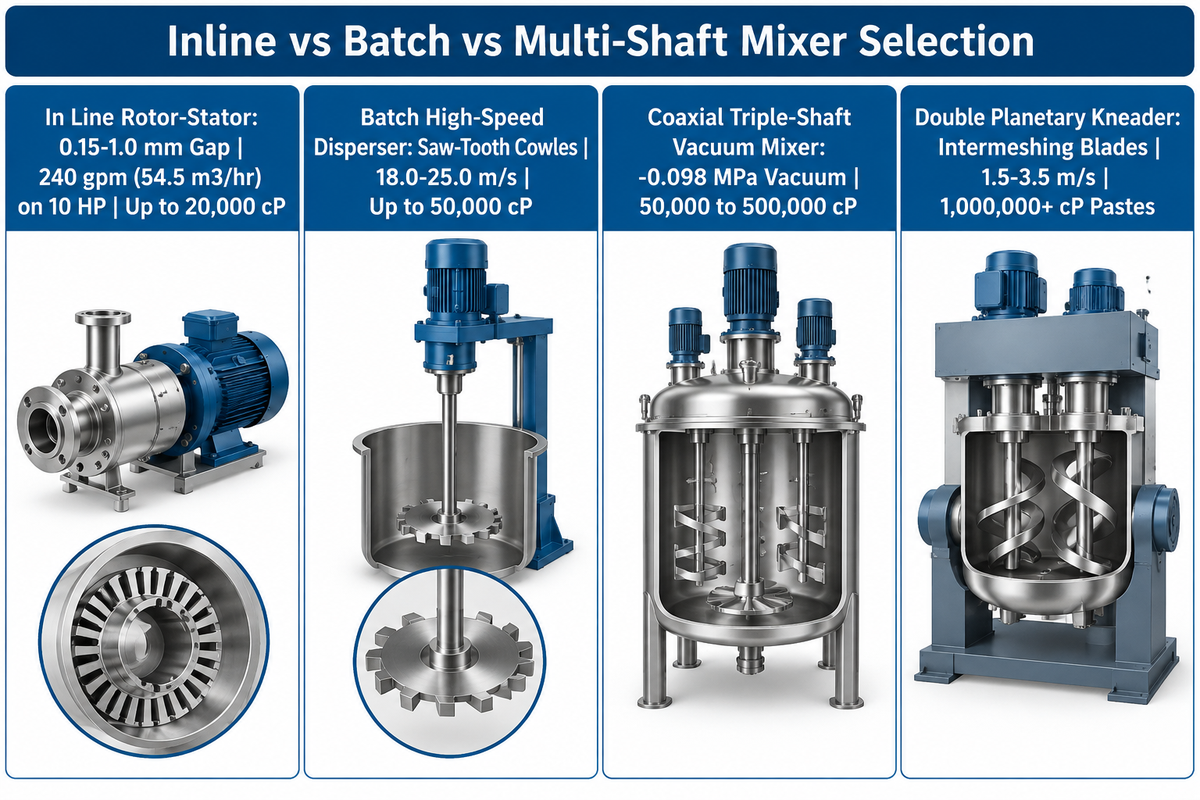
Select an in line mixer (high-shear rotor-stator) when impeller specific power must be concentrated in a pipeline for continuous mixing and rapid recirculation below 20,000 cP. Choose a batch high-speed disperser for pigment coatings at 1,000 to 50,000 cP. Specify a coaxial triple-shaft vacuum mixer when viscosity reaches 50,000 to 500,000 cP.
Choosing between an in line mixer and an in-tank liquid mixer depends on residence-time distribution, shear gap geometry, and cleaning turnaround. As revealed in US Patent US6000840A on high-shear rotors and stators, an inline rotor-stator mixer processes fluid through a precision rotor-stator shear gap of 0.15 to 1.0 mm. Every fluid packet passing through the working head experiences mechanical and hydraulic shear.
| Process Metric & Operating Boundary | In Line Rotor-Stator Mixer | Batch High-Speed Disperser | Coaxial Triple-Shaft Vacuum Mixer | Double Planetary Kneader |
|---|---|---|---|---|
| Shear Zone Geometry | 0.15–1.0 mm precision rotor-stator gap | Open saw-tooth Cowles disc rim | Anchor scraper + disperser + rotor-stator | Intermeshing twisted planetary blades |
| Peripheral Tip Speed Range | 15.2–20.3 m/s (3,000–4,000 ft/min) | 18.0–25.0 m/s (up to 1,500–3,000 rpm) | 0.5–2.0 m/s anchor / 18–25 m/s shear | 1.5–3.5 m/s orbital revolution |
| Unassisted Viscosity Limit | 10,000–20,000 cP self-pumping | 50,000 cP in open or closed vessels | 500,000 cP with PTFE wall scrapers | 1,000,000+ cP high-solids pastes |
| Pump-Assisted Viscosity Ceiling | Up to 200,000 cP (Charles Ross auxiliary pump test) | Not applicable (batch vessel unit) | 500,000 cP (discharged via platen press) | 1,000,000+ cP (hydraulic ram discharge) |
| Typical Flow Rate / Turnover | 240 gpm (54.5 m³/hr) water-like fluid on 10 HP | 50–10,000 L batch turnover in 20–45 min | 100–5,000 L batch cycle in 45–90 min | 5–3,000 L heavy paste cycle in 60–180 min |
| Passes to Droplet Equilibrium | 5 to 10 recirculation passes | Continuous axial/radial donut circulation | Simultaneous macro-folding and micro-shear | Full-vessel planetary sweep every 3–5 rev |
| Vacuum De-Aeration Capability | Requires external vacuum receiving tank | Optional vacuum cover (-0.095 MPa) | Integrated vacuum vessel (-0.098 MPa) | Integrated deep vacuum (-0.098 MPa) |
| Clean-in-Place (CIP) & Changeover | High-velocity pipeline CIP (low hold-up) | Fast shaft lift and washdown between drums | Requires multi-angle spray lances | Change-can vessels minimize line downtime |
When an In Line Mixer Beats Batch Tanks for Continuous Emulsification and Subsurface Powder Induction
Choose an inline high-shear mixer for continuous mixing and rapid recirculation below 20,000 cP, and size it by flow rates rather than vessel volume. According to the Charles Ross & Son Company technical report on high-capacity rotor-stator mixers, a four-blade rotor turning at 3,000 to 4,000 ft/min (15.2 to 20.3 m/s) pumps 240 gallons per minute (54.5 m³/hr) of water-like fluid on a 10 HP motor. That single 10 HP unit can recirculate vessels from 25 gallons to 2,500 gallons.
An inline rotor-stator shears material passing through its working head. In continuous mixers, a recirculation loop provides multiple passes for the reduction of particle size distribution. Inline recirculation loops are explained in the IQS Directory engineering overview of high-shear mixers. As noted in the IQS Directory engineering overview of high-shear mixers , inline recirculation loops need 5 to 10 passes to reach droplet equilibrium across 1 to 10,000 cP. Charles Ross reports that inline rotor-stators can operate up to 10,000–20,000 cP without external pumping assistance and up to 200,000 cP with an auxiliary positive-displacement pump. While static mixers excel at low-viscosity continuous blending without moving parts, high-shear mixers use rotating blades for applications requiring sub-micron emulsions.
When a Batch Liquid Mixer or Coaxial Multi-Shaft Vacuum System Is Mandatory
Batch vessels are a practical choice for formulations with steep viscosity spikes, long reaction holds, or in-vessel vacuum degassing. A moisture-cured 250,000 cP sealant can be pumped through a suitably designed pipeline, with pressure drop determined by its rheology, flow rate, and pipeline geometry. A 250,000 cP moisture-cured sealant can be pumped through a suitably designed pipeline, with pressure drop determined by its rheology, flow rate, and the geometry of the pipeline. By switching to an in-vessel IDA triple-shaft mixer, a sealant plant uses a slow anchor with PTFE wipers to clean the jacketed wall. Simultaneously, a high-speed disperser and a rotor-stator head homogenize the batch under -0.098 MPa vacuum.
Selecting Dry Powder, Ribbon, and Solid-Liquid Incorporation Systems Without Dead Zones
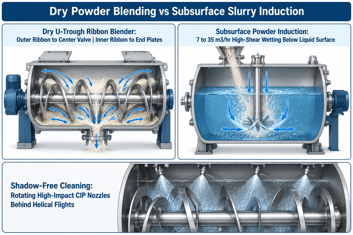
Use convective dual-helical ribbon blenders, paddle mixers, or tumbling drum blenders for dry free-flowing powders and fragile granules. Switch to a high-shear make-down system or a vacuum subsurface powder induction system operating at 7 to 35 m³/hr when wetting fumed silica, hydrocolloids, or high-solids slurries without floating dust or agglomerates.
Different phenomena happen in dry powder blending and solid-liquid slurry dispersion. In dry blending of materials, particle density differences trigger segregation if the agitator imparts excessive centrifugal force. In solid-liquid mixing applications, the primary failure mode is surface clumping (fish eyes) due to the formation of a gel skin around dry powder cores.
Dry Powder Blending, Convective Ribbon and Paddle Mixers vs. Tumbling Diffusive Blenders
Horizontal U-trough ribbon blenders use a double-helical mixing element. The outer ribbon moves solid particles toward the center discharge valve while the inner ribbon pushes material toward the end plates. Operating within the manufacturer’s rated working fill volume, ribbon and paddle mixers provide thorough mixing across dry powder batches. In the case of fragile and heat-sensitive food production ingredients, paddle mixers and tumbling drum mixers reduce attrition of particles.
Eliminating Floating Powder, Fish-Eyes, and Tank Dead Zones in Solid-Liquid Slurries
Dumping powders such as fumed silica and nanocellulose, through an open manway traps air and coats the upper shaft. According to US Patent Application US20230338999A1 on nanocellulose and resin make-down systems, high-shear units run at 7 to 35 m³/hr flow rates. They induct powder below the liquid surface right at the rotor tip, wetting each particle instantaneously.
The same principle applies to viscous solid-liquid tanks. Chemical engineering plant operators report that stationary spray balls leave uncleaned shadow zones behind wide helical ribbon flights, requiring rotating high-impact CIP nozzles or split-shaft couplings. Automated rotating CIP lances can improve spray coverage behind ribbon flights and reduce the need for manual cleaning between production runs.
Vessel Engineering, Mechanical Seals, Vacuum Degassing, and ATEX Acceptance Criteria
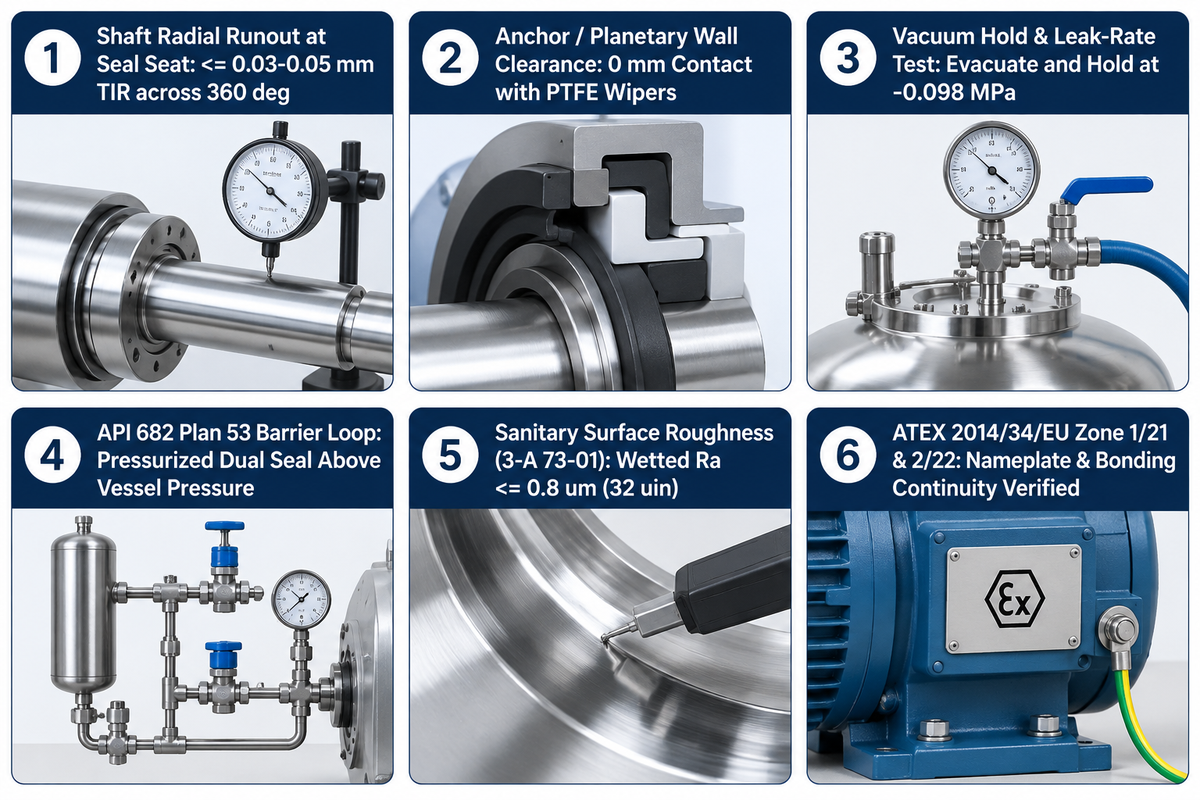
Pressurized or vacuum reactors can use API Standard 682 Arrangement 3 (Plan 53A/B/C) pressurized dual mechanical seals where process containment requires that arrangement. Pair them with 3-A 73-01 hygienic finishes (Ra at or below 0.8 μm) for sanitary lines and ATEX Directive 2014/34/EU Zone 1/21 motors for explosive atmospheres.
An advanced mixing drive fails rapidly if the mixing vessel, shaft bearings, and seal cartridge cannot handle thermal expansion and radial loads. Maintenance records confirm that most unexpected shutdowns of agitators in chemical plants are due to unpressurized seal flushing and runout of the shaft at the seal face.
Directive 2014/34/EU covers equipment and protective systems intended for use in potentially explosive atmospheres and defines the essential health and safety requirements for Zone 1/2 gas and Zone 21/22 dust.
Single vs. Pressurized Double Mechanical Seals (API Plan 53) and Shaft Runout Limits
Open-top atmospheric agitators use lip seals or single dry-running mechanical seals. Pressurized or vacuum chemical reactor vessels can use dual mechanical seals with a pressurized barrier fluid where process containment requires that arrangement, referencing API Standard 682 4th Edition seal flush plans. Under API 682 Arrangement 2 (Plan 52), an unpressurized buffer fluid vents fugitive vapors to a flare or recovery header. In a pressurized dual-seal system (Arrangement 3, Plan 53A, 53B, or 53C), barrier fluid held above maximum vessel pressure reduces process leakage across the inboard seal.
Vacuum Degassing Ratings, Jacketed Heat Transfer, ATEX Zone Protection, and FAT Checklists
In the manufacturing of lithium-ion batteries, structural adhesive and ointment, trapped micro-bubbles affect the dielectric strength and shelf stability of the product. Operating the vessel under -0.095 to -0.098 MPa vacuum during the final low-speed folding stage extracts entrained gas bubbles. For corrosive chloride slurries, upgrading the wetted shells from 316L to duplex stainless steel prevents stress-corrosion cracking.
Similar to the pharmaceutical plants, food plants aren’t exempt from strict hygiene standards and regulatory requirements. In February and April of 2026, 3-A Sanitary Standards, Inc. (3-A SSI) published updates to hygienic standards 3-A 00-02 and 3-A 73-01 pertaining to sanitary mixers and agitators. For sanitary mixer orders, 316L contact surfaces polished to a Ra value of 0.8 μm (32 μin) or finer can be specified as the wetted-surface acceptance criterion. Engineering teams verify custom mixers against a Factory Acceptance Test (FAT) checklist prior to shipment.
| FAT Inspection Item | Verification Method | Target Acceptance Criterion |
|---|---|---|
| Shaft Radial Runout at Seal Seat | Dial indicator across 360° slow rotation | ≤ 0.03–0.05 mm total indicator reading (TIR) |
| Anchor / Planetary Wall Clearance | Calibrated feeler gauge check around shell | Close-clearance metal gap (0 mm contact with PTFE wipers) |
| Vacuum Hold & Leak-Rate Test | Evacuate dry vessel to -0.098 MPa and isolate | Hold vacuum at -0.098 MPa per vessel specification |
| API 682 Plan 53 Barrier Loop | Hydrostatic and nitrogen accumulator hold test | Barrier pressure held above maximum vessel pressure |
| Sanitary Surface Roughness (3-A 73-01) | Calibrated profilometer + riboflavin CIP coverage | Wetted Ra ≤ 0.8 μm (32 μin); verified UV riboflavin wash |
| ATEX 2014/34/EU Electrical & Earthing | Nameplate audit + bonding resistance meter | Equipment marking for the specified gas or dust zone; bonding continuity against the installation specification |
Evaluating Industrial Mixing Equipment Manufacturers, Total Cost of Ownership, and Custom RFQs
Evaluate industrial mixing equipment suppliers by their machining capabilities, ISO 9001 quality management certification, applicable CE conformity documentation, ASME vessel documentation where specified, and pilot trial capabilities. Calculate total cost of ownership (TCO) by accounting for energy efficiency, seal maintenance intervals, batch cycle time, and the cost of controls that monitor and adjust mixer speed, rather than purchase price alone.
Selecting the right mixer requires looking beyond initial capital cost during equipment selection. A low-cost agitator that extends batch cycle time by 30 minutes or suffers frequent seal failures quickly erodes plant margin. Modern mixing technology also integrates computational fluid dynamics (CFD) and digital twin modeling, as shown in the MDPI Micromachines study on coaxial mixer digital twins, to predict shear distribution before fabrication.
Matching Full-Portfolio Manufacturers Across Dispersers, Coaxial Mixers, and Double Planetary Systems
A single impeller style may not suit all processes. Working with a multi-line manufacturer such as Jiangyin IDA Equipment Co., Ltd. Working with a multi-line manufacturer such as Jiangyin IDA Equipment Co., Ltd. lets engineers match the right mixer architecture to handle a wide range across fluid rheologies and wide range of fluid viscosities. IDA supplies high-speed dispersers, coaxial butterfly mixers, triple-shaft vacuum mixers, chemical reactors, and double planetary mixer systems across low-viscosity liquids and high-viscosity pastes. Clients can also refer to IDA’s equipment decision guide to align upstream dispersion with downstream milling.
Total Cost of Ownership (TCO) and Essential Data to Include in Your Mixer RFQ
Reducing total cost of ownership (TCO) is primarily the concern of the plant manager. “Games” like energy-efficient impeller and automated PLC control systems provide precise control over mixing to minimize variability and potential scrap in later processes, but can increase plant energy consumption. Automated recipe cutoffs can prevent over-mixing and reduce per-batch energy use; quantify any savings against the plant’s baseline.
Custom industrial mixer pricing and lead times depend on vessel volume, wetted alloy (304, 316L, or duplex stainless steel), vacuum rating, and ATEX motor certification. Final budget numbers will require an RFQ against the client’s viscosity curve and target quality of the final product. The six parameters are:
- Rheology and viscosity profile: Operating range of viscosity (cP) and non-Newtonian behavior.
- Phase composition and solids loading: Gravity of Liquid and bulk density of powder, weight percentage of solids, and target particle size.
- Working batch volumes (liters/gallons), minimum turn-down volumes, and target cycle times or flow rates (m3/hr) remain a top priority for manufacturers to ensure product consistency.
- Vessel pressure, vacuum, and thermal duty include internal pressure (bar), vacuum rating (-0.095 to -0.098 MPa), jacket heating/cooling media, and temperature range (°C).
- Wetted metallurgy and sanitary finish: 304, 316L, or duplex stainless steel, interior polish (Ra ≤ 0.8 µm per 3-A 73-01), and CIP spray-lance needs.
- Site utilities and hazardous area rating: Plant voltage/frequency, ATEX Zone 1/21 or Class I Div 1 motor certification, and PLC/SCADA interfaces.
Frequently Asked Questions About Industrial Mixing
What is an industrial mixer and how does the mixing process work?
An industrial mixer is a powered machine that uses rotating impellers, high-shear rotor-stator heads or planetary blades to blend liquids (suspend solids) or knead heavy pastes. In industrial mixing processes, the drive motor provides the shaft torque that creates axial flow for tank turnover, and blades create velocity gradients and shear forces that break up particles.
What are the three main types of industrial mixers?
The main types of industrial mixers are turbulent tank agitators, high-shear dispersers, and laminar positive-displacement kneaders. Turbulent agitator mixers use axial hydrofoils, propellers, or pitched-blade turbines for 1 to 10,000 cP liquids. High-shear Cowles dispersers and rotor-stators run at 18–25 m/s and handle viscosities up to 50,000 cP, while coaxial and double planetary mixers handle 50,000 to 1,000,000+ cP pastes.
What type of equipment is used for mixing powder into high-viscosity liquids?
For high-viscosity powder incorporation, vacuum powder induction can feed a batch vessel. Charles Ross reports pump-fed inline rotor-stator processors can process up to 200,000 cP. For heavier batches, coaxial triple-shaft vacuum mixers can cover batches up to 500,000 cP, while double planetary vacuum mixers can process pastes up to 1,000,000 cP and higher. These specialized mixers pull powders to below the liquid level to remove floating dust, dead zones, and hydrated fish eyes.
How do agitator mixers compare to static mixers and inline rotor-stator mixers?
Agitator mixers use tank-mounted shafts for flexible batch holding and chemical reactions. In the case of a system with miscible fluid, static mixers use pipe elements for low energy pipeline blending. An inline rotor-stator mixer shears material passing through its 0.15 to 1.0 mm working gap, and recirculation loop provides 5 to 10 passes for particle or droplet size reduction.
What role do batch size, viscosity, and shear rate play when requesting a custom mixer quote?
Batch size determines vessel geometry and impeller diameter ratio (D/T = 0.20–0.60 for turbines; 0.90–0.98 for anchors and planetary blades). Viscosity dictates Reynolds number and whether turbulent pumping or laminar planetary kneading is required. Shear rate defines required tip speed (0.5 to 25 m/s) and specific power (0.1 to 5.0 kW/m³) so the motor avoids overload.
Need Engineering Support for Your Next Industrial Mixing System?
Jiangyin IDA Equipment Co., Ltd. designs and manufactures high-speed coaxial butterfly mixers, triple-shaft vacuum mixers, and double planetary systems for low-viscosity liquids and high-viscosity paste formulations. Contact IDA Equipment’s process engineering team with your viscosity curve and batch volume for a custom configuration and trial test.
References & Sources
- ChE 344: Mixing in Chemical Reactors, Impeller Classification University of Michigan Department of Chemical Engineering.
- Tackling Difficult Mixing Problems (Chemical Engineering Progress) American Institute of Chemical Engineers (AIChE).
- Reynolds Number and Impeller Diameter Effects on Instabilities in Stirred Vessels AIChE Journal (Wiley).
- Effect of Impeller Type and Number and Liquid Level on Turbulent Blend Time University of Dayton Graduate Theses.
- Power Consumption and Mixing Intensity in Stirred Tanks MDPI Energies Peer-Reviewed Journal.
- A Digital Twin of the Coaxial Lamination Mixer for Systematic Process Design MDPI Micromachines Peer-Reviewed Journal.
- “What is Good Mixing? Flow Patterns, Baffles, and Impeller Selection” from Chemical Engineering Magazine
- 3-A Sanitary Standards 00-02 and 73-01 Hygienic Agitator & Shear Mixer Updates (2026) — 3-A Sanitary Standards, Inc.
- “Equipment for Explosive Atmospheres (ATEX Directive 2014/34/EU Harmonised Standards)” from the European Commission.
- “US Patent US6000840A: Rotors and Stators for Mixers and Emulsifiers” from the United States Patent and Trademark Office (Google Patents).
- “US Patent Application US20150224460A1: Distributed Planetary Mixing Apparatus” from the United States Patent and Trademark Office (Google Patents).
- “US Patent Application US20230338999A1: High-Shear Solid-Liquid Make-Down Systems” from the United States Patent and Trademark Office (Google Patents).