Get in Touch with IDA


Axial flow means fluid moves mainly parallel to a shaft or rotation axis. A pump moves liquid through a system; a tank impeller circulates liquid within a vessel. For mixing, use a blade suited to the required circulation, shear and suspension duty.
A replacement impeller can look correct and still leave powder under a bottom valve. Another can circulate the batch well but damage a shear sensitive ingredient. This guide includes the basic definition and blade selection, a diameter and speed calculation, and the costs that belong in an equivalent quote.
Quick selection: Start with axial circulation for liquid blending and appropriate suspension duties. Separate agglomerate breakup from bulk movement. For a very viscous fluid that barely mixes at the wall, investigate a close-clearance mixing arrangement. Compare alternatives against the same finished product requirement, vessel and operating liquid level.
What Is Meant by Axial Flow?
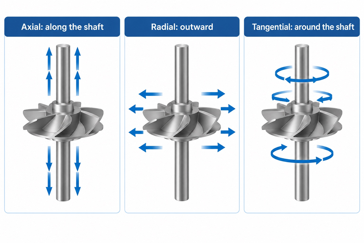
Axial flow describes the principal flow direction along the axis of rotation of a machine. Imagine looking along a shaft: fluid flows axially toward or away from you, and radially outward across your view. A working flow field can contain both components, plus tangential motion around the shaft. The overall effect of these local movements is flow of fluid.
What does axial mean in physics?
“Axial” means aligned with an axis chosen to describe motion or geometry. For rotating equipment, that reference is normally the axis of the shaft. The term describes where the fluid is flowing with respect to that line. The equipment design dictates if the result is transport, ventilation, compression, or mixing within a vessel.
In a tank, an axial impeller moves liquid along the axis before the vessel redirects it to a return path. The University of Michigan’s Impeller Types teaching page distinguishes this pattern from radial discharge, which is perpendicular to the axis. This same page identifies propellers and pitched blade turbines as axial mixing geometries.
Outside a mixing vessel, the function changes. An axial flow pump moves liquid through its casing. Axial fans move air through a passage, often for ventilation; an axial flow fan still needs selection against the resistance of that passage. An axial-flow compressor increases gas pressure through successive blade rows. NASA’s axial compressor explanation describes rotating rotors and stationary stators with airflow along the rotation axis.
The rotating blades exchange energy with the flow entering the machine. In an axial compressor, gas enters through the inlet and continues through alternating blade rows. Stationary blades redirect that moving gas between rotor rows. NASA states that pressure increases throughout the machine, while the stators redirect swirl. Required air pressure and the operating conditions belong in the compressor specification. The two types of compressors NASA compares, axial and centrifugal, produce that increase in pressure with different flow paths.
When a tank blade is replaced, the required mixing duty should determine whether an axial mixing impeller is ordered. Pump flow capacity and compressor pressure ratios also answer different questions. Normally, start specifications with the type of material and the goal of the process to help the supplier identify the correct family of machines.
Axial Flow vs Radial Flow: Direction Before Device
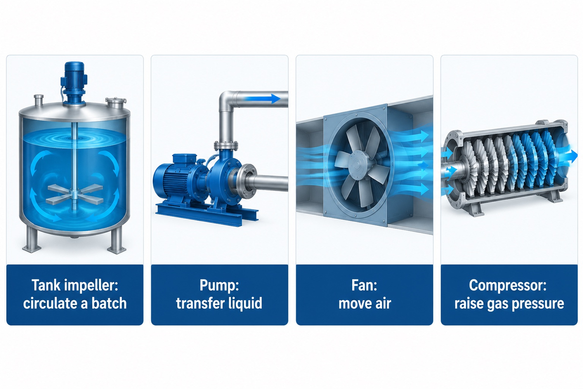
Axial and radial flow differ in the principal discharge direction relative to the shaft. The University of Michigan’s impeller classification describes these axial and radial discharge patterns. In a stirred tank, either pattern of flow can form circulation loops after the liquid meets a wall, base or surface. The useful performance of those loops depends on how well they distribute the material and energy through the actual working volume of the vessel, including areas far from the blades.
What is the difference between axial flow and centrifugal flow?
Axial flow follows the direction of the shaft; centrifugal equipment accelerates fluid outward from an impeller. In a centrifugal pump, liquid is drawn into the impeller and is discharged radially into the casing. A tank mixer discharges into the same vessel, which isn’t the case for a delivery pipe.
Describing centrifugal force, pressure energy or a pump’s volute is part of pump operation. Comparing those head-and-flow diagrams to tank mixing can produce a misleading specification. Likewise, a radial flow pump and radial flow impellers in a batch vessel also share a direction word, but have different performance characteristics.
Radial pump discharge travels outward; a mixed-flow design combines an axial and outward path. A high volume at low pressure is a different duty from a smaller delivery against high pressure. A low-pressure transfer and a high-pressure delivery therefore require different operating point comparisons. The required volume flow and system resistance set the comparison, rather than the direction word by itself. A mixed-flow pump can suit duties with substantial volume and moderate pressure when its operating curve matches the system.
Discussions on pumps distinguish kinetic energy from the pressure recovered through stationary passages like a diffuser. Each vane is a physical blade or guiding surface; “radial and axial” refers to relative motion with respect to the shaft. Consider hardware, flow direction, and useful output separately when interpreting a supplier drawing.
| Flow description | Principal direction | Useful mixing question |
|---|---|---|
| Axial | Parallel to the axis | Does the return loop sweep the required batch volume? |
| Radial | Outward from the axis | Does the local discharge support the required shear or dispersion? |
| Tangential | Around the axis | Is the batch rotating together while weak exchange remains elsewhere? |
| Mixed flow | Axial and radial components | Which component reaches the region that controls product quality? |
“Pure axial” describes discharge in a simplified fashion and doesn’t claim that all liquid parcels move in the same way along the length of the shaft. The closed return loop necessarily changes direction; the number of blades, their profile and tank geometry affect that motion.
High-volume delivery and high efficiency are separate requirements, too. A comparison should identify the useful output and energy input at the duty in question. An energy-efficient selection matches the useful output to its energy input. A high flow label gives no electricity-cost comparison between a pump, a fan and an open-tank mixer because those machines perform different work.
Illustrative scenario: A purchaser asks for high flow rate after seeing a pump catalog. The process engineer instead needs a dissolved additive to reach the bottom sample point before filling begins. A mixing proposal should describe that concentration endpoint and sampling arrangement; a pipe delivery flow rate would omit that essential requirement.
How Axial Flow Impellers Circulate a Mixing Tank
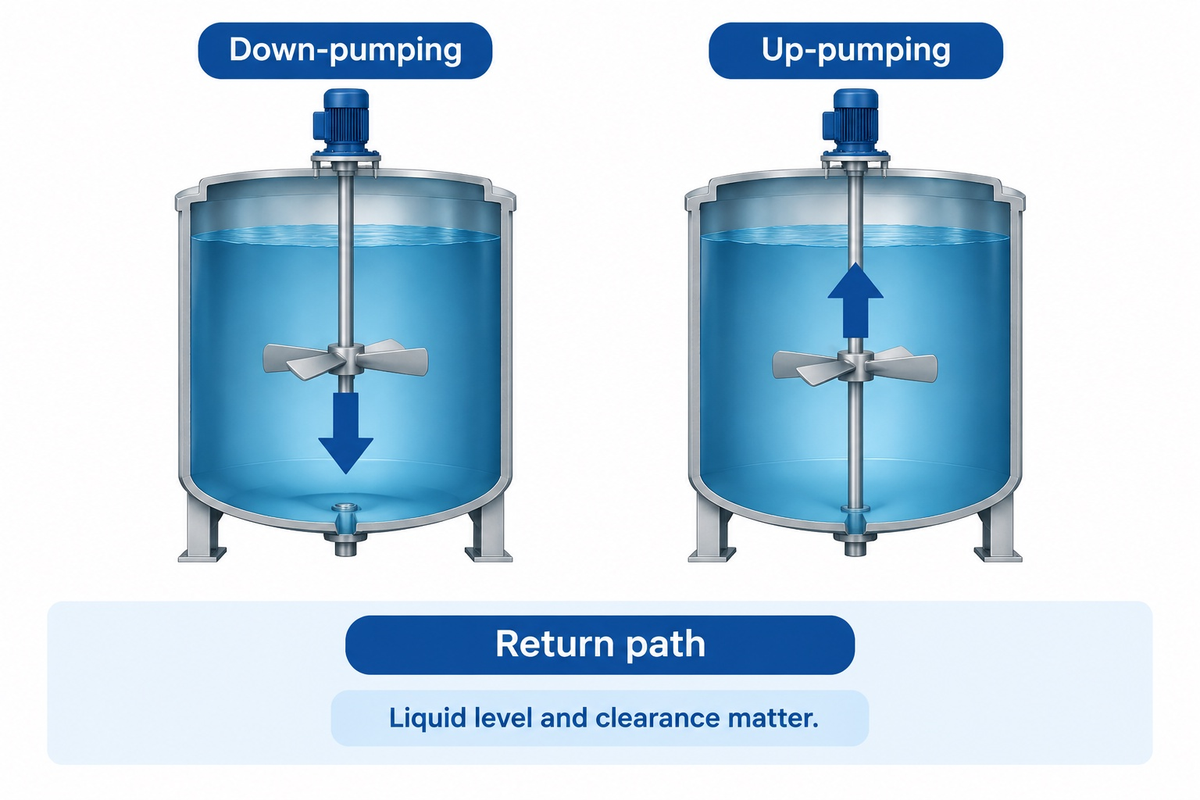
Axial flow impellers result in an axial discharge with a vessel-wide return route. Down-pumping sends the main discharge to the bottom of the vessel. Up-pumping sends the main discharge to the top of the vessel. The position of the impeller, blade profile and vessel internals determine the closed return loop. Baffles, liquid level and impeller clearance all belong in the selection discussion because they redirect that returning liquid.
With a down-pumping arrangement, liquid reaching the lower vessel must turn outward and return toward the impeller intake. A bottom pocket, internal coil, or improperly placed feed point can interrupt this exchange. Looking only at the liquid immediately around the rotor misses the part of the route that matters to the batch.
Increasing bottom clearance can also change the pattern of circulation. In Wong and colleagues’ study of impeller-to tank geometry, increasing bottom clearance split the circulation of the tested pitched-blade and propeller designs into separate loops with weaker lower circulation and center accumulation. Another tested geometry maintained its axial flow across the clearances studied. This result indicated that clearance is a process variable, and not just an installation variable.
Up-pumping designs are also available. SPX’s axial-flow catalog offers an up-pumping hydrofoil, A340, in addition to the A310 and A510 hydrofoils, and the A200 pitched blade turbine. These names refer to the corresponding families manufactured by the company. A turbine impeller from another supplier can have a different blade profile and approved direction of rotation.
The suspended-solids demonstration by ProQuip distinguishes sinking from floating materials and uses a specific baffled-tank design. A useful lesson to take from this is to introduce useful liquid motion either where the material enters the batch or where it accumulates. This demonstration is provided to illustrate the principle, not to instruct anyone to reverse previously implemented drive units.
When assessing alternatives for a retrofit, record the current rotation direction, blade handedness and location. When considering a change in rotation direction, axial thrust can change and affect the load carried by the shaft support. The proposed arrangement needs to fit the existing bearings, attachment and drive as well as produce the desired fluid motion.
Thin liquid at full working level and the same vessel near its minimum operating level present different flow paths. Quote both levels. Otherwise, a layout selected around a large volume of liquid may perform poorly during a short batch or the final transfer stage.
Hydrofoil or Pitched Blade Turbine: Which Fits the Duty?
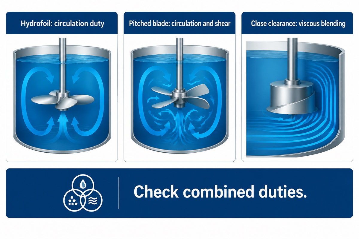
Circulation duty can be better handled by a hydrofoil and combined circulation- and shear-duty can be handled better by a pitched-blade turbine. A comparison of actual designs at the same process endpoint will help us choose the right arrangement. The viscosity of the liquid and solids behavior as well as the shape of the vessel can affect the preferred arrangement. Neither of the two blade families has a universal energy-saving percentage or a universal suspension limit.
The “Circulation-Shear Split” refers to moving material around the tank as compared to changing it locally. A dissolved ingredient needs distribution. A pigment agglomerate may also need breakup. Fragile cells impose a damage constraint while still requiring nutrient and oxygen distribution. Treating every case as “more mixing” can obscure real competing requirements.
| Duty | Starting comparison | Constraint that changes the choice |
|---|---|---|
| Miscible liquid blending | Axial circulation designs | Concentration uniformity at remote sample points |
| Settling solids | Bottom-reaching circulation | Particle settling and the required solids distribution |
| Floating powder | Surface incorporation and return path | Powder raft and feed location |
| Fragile biological material | Circulation with a shear constraint | Cell damage versus mass transfer |
| Agglomerate breakup | Dispersion element plus circulation | Particle-size endpoint |
| Gas dispersion | Gas-handling impeller arrangements | Gas distribution and transfer at the stated gas rate |
| Aerated solids suspension | Combined gas-liquid-solid duty | Suspension stability, torque fluctuations and gas rate |
| Viscous laminar blending | Close-clearance mixing geometries | Wall-to-bulk movement |
| Narrow tote access | Folding-access arrangement | Opening, internal clearance and support |
| Reaction heat transfer | Bulk circulation and wall-region movement | Temperature gradients around heat-transfer surfaces |
For a specific product example, Fusion Express lists its 9-inch PF3 hydrofoil with a power number of 0.3 and a flow number of 0.5. These can’t be assumed to be design coefficients for every type of hydrofoil. They must be validated for the case in question.
Combined duties can change the preferred impeller. Ibrahim and Nienow’s aerated-suspension study found the tested down-pumping three-blade axial hydrofoils generally unsuitable for its gas-liquid-solid duty, while an up-pumping mixed-flow arrangement was stable in the tested fluids. This source-specific result rules out choosing an aerated slurry mixer from separate “solids” and “gas” labels alone.
For a batch of paint that requires pigment breakup, IDA’s high speed disperser for pigment breakup page describes a different piece of equipment to evaluate. A circulation element in the system can supply materials to a dispersion zone, and a dispersion element addresses the task of reducing particle size. Buying a circulation blade alone can leave that second duty unfinished in industrial processes that combine blending with dispersion.
University teaching treats ribbon, screw and anchor geometries that interact with the vessel wall for highly viscous laminar fluids. Sepro states that viscous mixing can deviate from the conventional impeller wisdom. Therefore, a low-shear specification should include how the actual material behaves near the wall and at the bottom.
Impeller Size, Speed and Power: A Worked Comparison
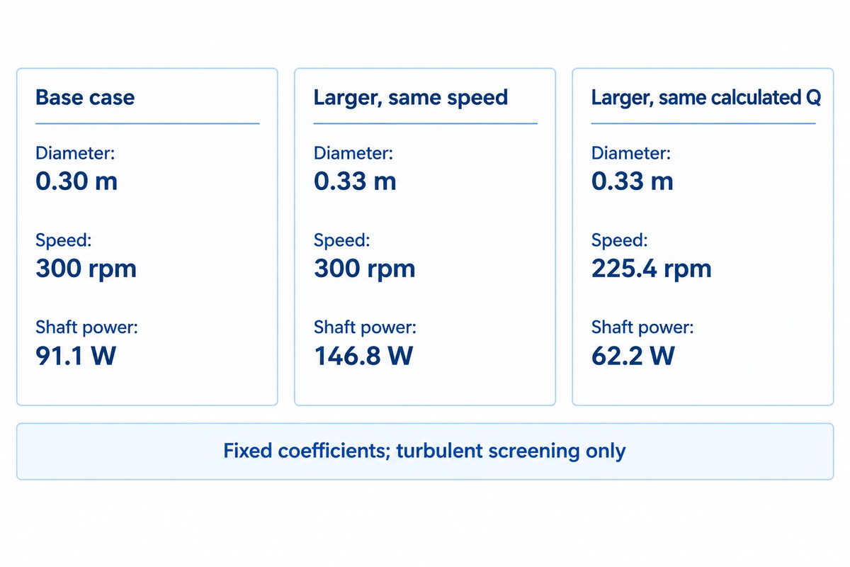
Under unchanged turbulent-flow coefficients, increasing impeller diameter by 10% at constant rotational speed raises calculated discharge by 33.1% and shaft power by 61.1%. Holding the same calculated discharge instead lowers speed from 300 rpm to about 225.4 rpm and reduces calculated shaft power by 31.7%. This is a conditional screening calculation, not a measured retrofit saving.
The Diameter-Speed Exchange uses the University of Michigan dimensionless-number definitions. Write discharge as Q = Nq × N × D³ and shaft power as P = Np × ρ × N³ × D⁵. Here N is revolutions per second, D is diameter in meters, Q is m³/s and ρ is density in kg/m³.
Take assumed inputs as D = 0.30 m, N = 300 rpm = 5 revolutions per second, ρ = 1,000 kg/m³, Nq = 0.5 and Np = 0.3. The coefficients are illustrative inputs drawn from the listed PF3 product. This hypothetical geometry isn’t a quotation of that product. Calculations yield Q = 0.0675 m³/s and P = 91.125 W at the shaft.
The example supposes a fully turbulent flow regime and fixes both coefficients for simplicity in the calculations. Actual flow conditions and vessel geometry determine their applicability. Lower calculated power for a given discharge still requires a separate comparison with respect to suspension, shear and mechanical loads prior to any retrofit decision.
| Variable | Base case | Larger, same speed | Larger, same calculated Q |
|---|---|---|---|
| Diameter | 0.30 m | 0.33 m | 0.33 m |
| Speed | 300 rpm | 300 rpm | 225.4 rpm |
| Discharge ratio | 1.000 | 1.331 | 1.000 |
| Shaft-power ratio | 1.000 | 1.611 | 0.683 |
| Calculated discharge | 0.0675 m³/s | 0.0898 m³/s | 0.0675 m³/s |
| Calculated shaft power | 91.1 W | 146.8 W | 62.2 W |
The equal-Q speed ratio is 1/1.1³; substituting it into the power relationship gives a power ratio of 1/1.1⁴. This explains why comparing blades only at equal rpm can miss a useful size-and-speed tradeoff. Electrical input also includes drive losses, so the shaft-power numbers are not electricity bills.
Equal impeller discharge can result in a different blend time and/or solids distribution. Therefore, the calculation must be corroborated by a process check against bottom velocity, shear, clearance and flow regime. Maintenance also needs a shaft-load check: a larger blade may fit through the opening yet exceed the existing mechanical arrangement’s allowable loading.
Why Visible Motion Can Leave Solids and Dead Zones
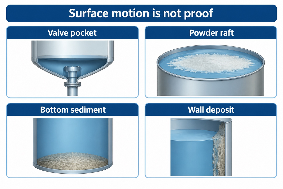
A moving surface can coexist with weak (or no) movement close to the base, wall or bottom valve. Diagnose the location of the failed duty rather than judging the whole batch by its most visible region. For suspension, distinguish lifting solids from the floor from distributing them throughout the working volume; those are different acceptance endpoints.
A 2015 Eng-Tips post outlines bottom valve obstructions caused by reagent solids in a reactor with a pitched turbine. Replies discuss local flow and feed conditions, and 1gibson raises axial thrust and bearing loading when changing direction. This is an attributed practitioner account, rather than an IDA customer case or a controlled comparison.
Illustrative scenario: A slurry looks mobile during mixing, but the first material discharged from the bottom has a different solids concentration. Production needs samples tied to the filling sequence; maintenance needs to inspect the valve pocket and discharge path. Increasing speed without locating the weak region may consume more power while leaving the release problem unresolved.
| Observed problem | Region or variable to inspect | Useful acceptance record |
|---|---|---|
| Bottom-valve obstruction | Valve pocket and local solids feed | Obstruction frequency and deposit location |
| Bottom sediment | Bottom sweep and particle settling | Residual bed and sample solids content |
| Floating powder raft | Surface return and powder addition | Incorporation time at the stated feed rate |
| Uneven concentration | Exchange between remote regions | Sample positions and concentration spread |
| Foam or air pickup | Surface drawdown and liquid level | Foam behavior during the actual batch cycle |
| Wall-adhering material | Rheology and wall-region motion | Deposit location after the trial |
| Persistent agglomerates | Local dispersion duty | Particle-size or dispersion endpoint |
| Motor overload | Fluid condition and shaft power | Load at the maximum specified viscosity |
| Vibration after retrofit | Support, balance and hydraulic loading | Mechanical assessment at operating conditions |
When one vessel needs circulation plus another mixing action, compare the arrangement with a triple shaft mixer. For thick material requiring a different movement pattern, the double planetary mixer is another family to assess. Match the equipment comparison to the failed process duty rather than treating these machines as interchangeable blades.
Axial Flow Impeller Cost and Supplier Options
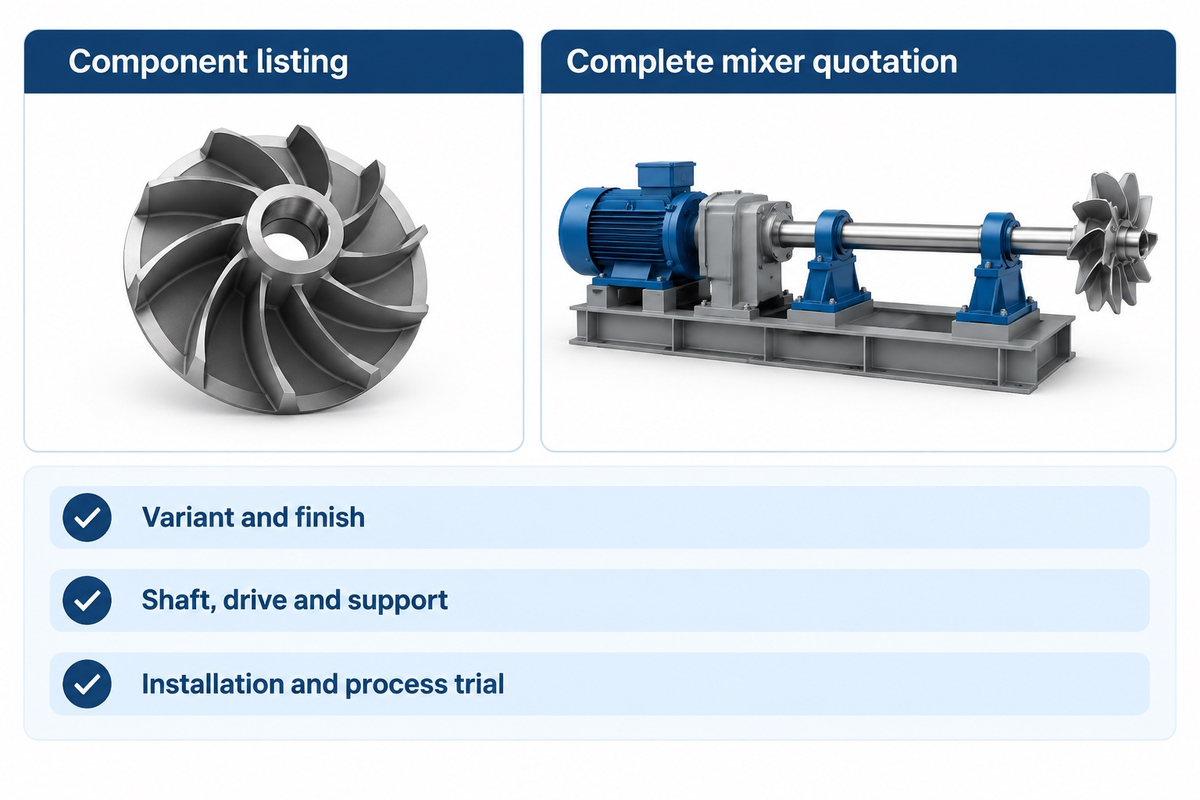
Mixer Direct’s catalog lists axial turbine components from $300 for a 4-inch diameter with a 5/16-inch bore to $2,613 for a 40-inch diameter with a 2.5-inch bore, as checked on October 28, 2026. These are component listings. A complete mixer quotation must separately state its shaft, drive, mounting, controls and installation scope.
| Supplier listing | Exact listed variant | Published price |
|---|---|---|
| Mixer Direct axial turbine | 4 in diameter; 5/16 in bore | $300 |
| Mixer Direct axial turbine | 12 in diameter; 1.25 in bore | $491 |
| Mixer Direct axial turbine | 24 in diameter; 1.75 in bore | $905 |
| Mixer Direct axial turbine | 40 in diameter; 2.5 in bore | $2,613 |
| Fusion Express PF3 hydrofoil | 9 in diameter; standard mill finish | $355 |
| Fusion Express PF3 hydrofoil | 9 in diameter; listed 32Ra finish option | $557 |
| Fusion Express PF3 hydrofoil | 9 in diameter; listed 20Ra finish option | $815 |
| Fusion Express PF3 hydrofoil | 9 in diameter; listed 8Ra finish option | $1,010 |
The PF3 finish options illustrate the inadequacy of a diameter-only comparison. Preserve the bore, material and surface-finish requirement when asking for alternatives. A commercial finish label is a product option; the purchaser’s cleaning and process requirements govern acceptance.
Compare supplier scope in separate lines: impeller and attachment; shaft and supports; motor and gearbox; seal; vessel mounting; speed control; documentation; freight; installation; commissioning; and the agreed process trial. A less-expensive replacement blade can become a more costly retrofit if the existing shaft and/or mounting also need to be replaced.
Illustrative scenario: The process engineer specifies the same fluid conditions and end point for both suppliers; maintenance checks which existing parts each proposal assumes can be left in service. Finance needs a scope definition to reconcile totals before comparing costs. Purchasing receives a quote for a bare hydrofoil and a quote for a mixer with a drive and support bridge.
Match Axial Circulation to IBC, Disperser and Reactor Duties
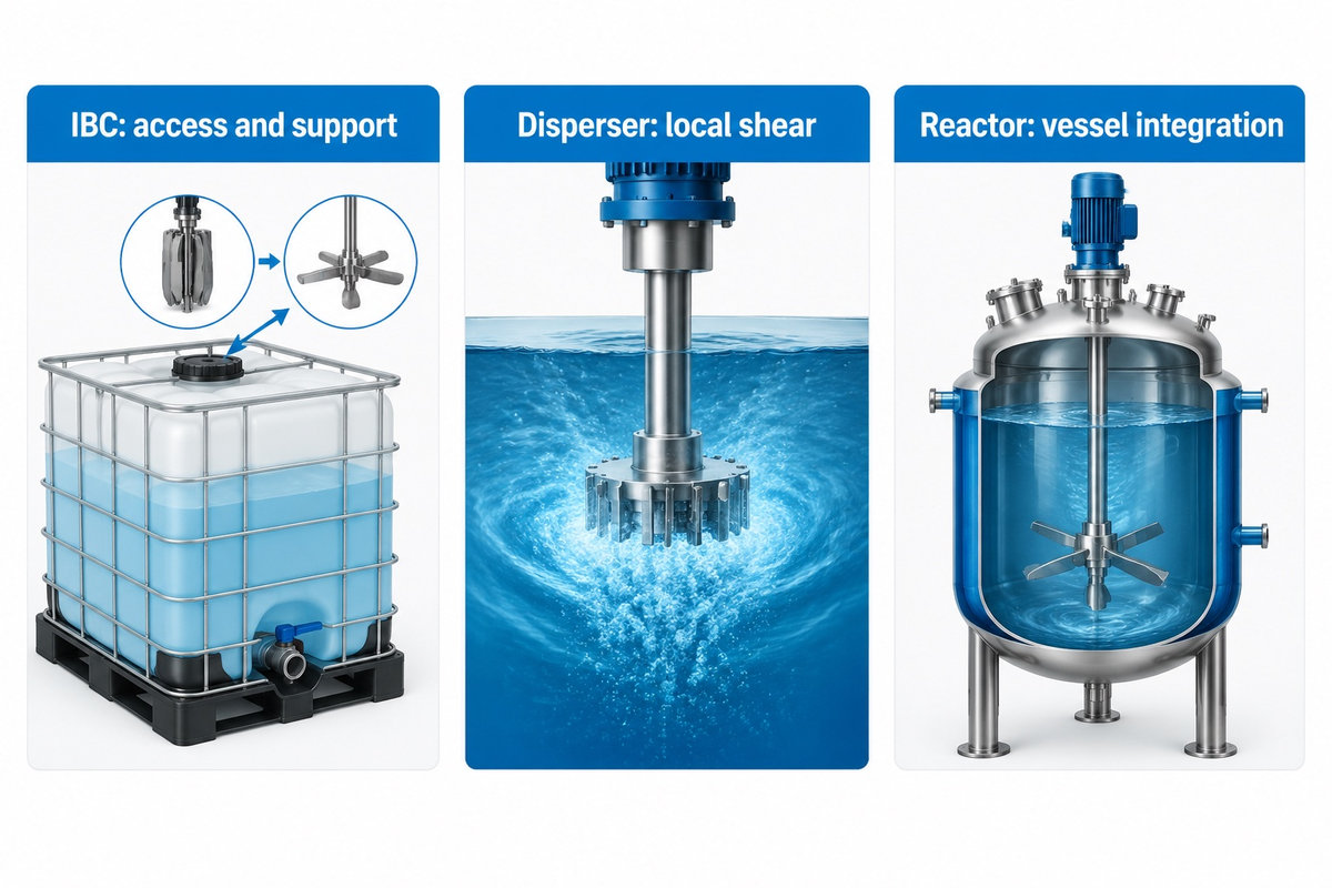
Select the family of equipment based on access, behavior of the material, and stage of the process. Tote blending starts with the opening and supporting arrangement. Dispersion adds a local shear requirement. A reactor adds vessel integration and heat transfer considerations. The same word “axial” appears in all the cases, but the required equipment and acceptance test differ.
IDA’s IBC tank mixer page describes a folding-access concept for a nominal 150 mm or 6-inch opening. Check the actual opening and internal obstruction drawing when specifying the assembly: those are alternative nominal descriptions, not exact converted dimensions. The unfolded blade and shaft must also suit the tote geometry.
A coating line may need circulation while ingredients are added, followed by a separate dispersion task. Viscosity and liquid level of the batch may vary and affect the mixing requirement in a reaction vessel. IDA’s chemical reactor page is the commercial destination for discussing vessel integration once the process conditions are defined.
When making a preliminary inquiry, the user must define the working volume range, density and viscosity at operating temperature, the description of the solids, addition sequence, and desired end point. Include a drawing with the bottom outlet and internals. This gives the supplier a defined duty to quote and gives the buyer a basis for comparing the proposed configuration.
What Current Mixing Research Means for Equipment Selection
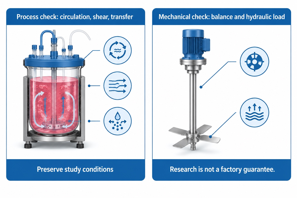
More recent mixing research invites comparison of circulation, shear and transfer at a defined duty, as opposed to selecting by blade name alone. A 2025 study evaluates these competing consequences for a stated reactor. Separately, mechanical design work distinguishes turbulent hydraulic forces from rotor imbalance. Together, these point to both process and mechanical checks in a retrofit.
The Scientific Reports study by Manickavasagam and colleagues, published March 18, 2025, compares setric, marine and Rushton impellers for non-Newtonian Viola odorata cell suspension. Its baseline flow comparison and its equal-bottom-velocity comparison use different operating conditions. The conclusions concern that cell-culture system, rather than paint or resin production.
In particular, the equal-bottom-velocity comparison uses setric at 85 rpm, Rushton at 330 rpm and marine at 300 rpm. Comparing “which mixes better” without preserving those conditions would change the meaning of the result. The authors acknowledged CSR funding from Hyclone/Cytiva and L&T Technology Services, and declared no competing interests.
Greg T. Benz’s November 2025 Chemical Engineering discussion of agitator hydraulic force explains that turbulent side loads have a source distinct from mechanical imbalance.
“The calculations presented here will be based on turbulent flow.”
The ISO 21940-11:2016 public catalog concerns balancing rotors with rigid behavior and lists Amendment 1:2022. Balancing and hydraulic load assessment address different mechanical concerns. A retrofit proposal should consider both the mechanical adequacy of the assembly and the required mixing result.
Frequently Asked Questions
What are axial-flow pumps used for?
Axial-flow pumps transfer large liquid volumes where the required head suits the selected pump design.
Key Differences. Common applications include irrigation and water-circulation duties. These propeller pumps are associated with low head and high-volume transfer. A purchaser specifies flow rate and system head, then checks the manufacturer’s operating curve. These pump requirements differ from selecting an open impeller to circulate a batch inside a mixing tank.
What is an axial-flow compressor?
An axial-flow compressor raises gas pressure while the main airflow travels along its rotation axis.
NASA describes successive rows of rotating rotor blades and stationary stator blades. The blade rows control the flow and pressure rise through the machine. Compressor design includes gas behavior and operating limits which don’t transfer directly to a liquid mixing impeller.
What is the difference between a stator and a rotor in an axial flow compressor?
The rotor turns with the shaft; the stator remains stationary.
NASA states that stators increase pressure and redirect spiraling flow toward the axial direction between the rows of the rotor. Both blade sets shape the flow through the machine, and their arrangement describes a compression machine, not a conventional open-tank mixing assembly.
Can reversing rotation reverse axial pumping direction?
Yes, reversing rotation can reverse axial pumping, if the impeller design and approved drive arrangement permit it.
A purpose-built up-pumping hydrofoil differs from an arbitrary reversed installation. Blade profile, attachment and axial thrust must remain compatible with the shaft supports. Obtain the approved drive arrangement from the supplier before changing the motor rotation.
Is one tank turnover the same as complete mixing?
No. One calculated turnover describes the volume of liquid divided by the selected circulation rate, while true complete mixing requires a defined uniformity end point.
Fluids can revisit a circulation loop while remote regions exchange more slowly. The process specification should state sampling locations, allowable concentration variations, and operating conditions. Impeller discharge alone can’t give the acceptance result, especially if material contains solids that can settle or if the material has a strong viscosity gradient.
Can an axial impeller replace a high-speed disperser?
An acceptable axial impeller can replace a disperser only if the process requires circulation without the disperser’s function to break up particles.
The required particle size at the endpoint of a dispersion should be evaluated along with the local shear. Some processes can’t function without a circulation element in addition to the dispersion element.
What is a hydrofoil impeller?
A hydrofoil impeller uses profiled blades to create a designed liquid discharge, commonly for axial circulation in mixing vessels.
Stipulations like blade geometry, mounting, viscosity, and the process goal still dictate choice. For power and pumping data, check your specific product’s spec sheet at the applicable conditions. The required endpoint for blending and solids distribution is product and application specific and is determined in a product trial.
Conclusion: Specify the Mixing Duty Before the Blade
For liquid blending, begin with the required circulation and uniformity endpoint. Add the solids, shear and wall-movement constraints that affect your batch. Send IDA the fluid conditions, a vessel drawing, and the details of your existing drives to discuss a mixing duty. Request a configuration and a trial to address the constraints identified.
References & Sources
- University of Michigan, Impeller Types, Mixing in Chemical Reactors teaching material.
- University of Michigan, Dimensionless Numbers, including the power- and pumping-number equation diagrams.
- S. D. Wong and colleagues, Effect of Impeller-To-Tank Geometry on Particles Distribution and Just-Suspension Speeds for a Range of Solids Loadings, university research record and abstract.
- S. Ibrahim and A. Nienow, The Effect of Viscosity on Particle Suspension in An Aerated Stirred Vessel With Different Impellers and Bases, Chemical Engineering Communications, 2010; university research record and abstract.
- NASA Glenn Research Center, Axial Compressors, updated May 13, 2021.
- Manickavasagam and colleagues, Characterizing the effect of impeller design in plant cell fermentations using CFD modeling, Scientific Reports 15, 9322, March 18, 2025.
- Gregory T. Benz, Agitator Impeller Hydraulic Force in Mixing Vessels, Chemical Engineering, November 1, 2025.
- International Organization for Standardization, ISO 21940-11:2016 public catalog and amendment listing, procedures and tolerances for rotors with rigid behavior.